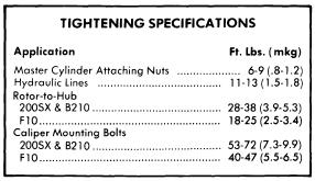
Showing posts with label brake. Show all posts

How to Replace Your Front Brake Calipers 1992 Chevy Cavalier

| 0 comments |
How to Replace Your Front Brake Calipers:1992 Chevy Cavalier
Instructions on replacing your front brake calipers. You will need to bleed the calipers when you are finished.
Read More..

Datsun F10 200SX B210 1976 77 Brake Repair Manual

| 0 comments |
DESCRIPTION
Brake system is hydraulically operated, utilizing a tandem master cylinder and a Master-Vac power brake unit. Front disc brakes consist of rotors attached to wheel hubs, and single cylinder, dual-piston, floating-calipers attached to steering knuckles. Rear brakes are leading-trailing shoe/drum type, using a single piston sliding wheel cylinder. Parking brake is cable actuated; operating wheel cylinders of rear brake assemblies.

ADJUSTMENT
PEDAL HEIGHT & FREE PLAY
F10 - Adjust pedal height to 6.8-7.0" (172-178 mm) by turning nut on master cylinder push rod. Adjust stop light switch so pedal just touches end of stop light switch; tighten lock nut. NOTE - Brake pedal should be checked for travel and smooth operation. Travel should be 5-5.25" (127-133 mm).
200SX - Adjust pedal height to about 6.9" (175.5 mm) using stop light switch. Lock switch in place with retaining nut. After pedal height is adjusted, loosen push rod lock nut and adjust pedal free play to .039-.118" (1-3 mm).
B210 - Adjust pedal height to specifications by moving stop lamp switch. Pedal height should be 6.14" (156 mm) on vehicles equipped with manual transmission and 6.22" (158 mm) on vehicles with automatic transmission. After pedal height is adjusted, loosen push rod lock nut and adjust pedal free play to .039-.197" (1-5 mm).
FRONT DISC BRAKE PADS
Front disc brakes are self-adjusting, therefore, no adjustment in service is required.
REAR BRAKE SHOES
F10 - Raise and support vehicle. Pump brake pedal several times to center brake shoes. Using a screwdriver, turn adjuster star until considerable drag is evident. Back off adjuster five or six notches and make sure drum rotates freely.
200SX - No adjustment required.
B210 - Raise and support vehicle. Using a suitable brake adjusting tool, tighten adjuster eccentric clockwise until brake shoe contacts drum. Return adjuster eccentric until shoe is slightly separated from drum. Check operation by turning drum and applying brakes; if shoe interferes with drum rotation, readjust.
PARKING BRAKE
With rear brakes properly adjusted, adjust parking brake cable turnbuckle until rear brakes are locked when parking brake lever is pulled to sixth or seventh ratchet stop. Release parking brake lever and ensure rear wheels turn freely and that all parts are returned to their original position.
COMBINATION VALVE
Function Test, All Models - Accelerate engine to 30 mph and rapidly apply brakes. If rear wheels lock before front wheels, malfunction of combination valve assembly (200SX & B210), or of separate proportioning valve (F10) is indicated.
Warning Light Operation & Reset, Except 200SX - 1) Instrument panel light will come on when a pressure difference of between 71-224 psi is evident between front and rear hydraulic systems. Combination valve  shuffle moves to side of low pressure and grounds electrical circuit, causing warning light to come on.
2) When hydraulic problem has been corrected and brakes have been bled, system should have 427 psi. Shuttle will then return to position and light will go out.
HYDRAULIC SYSTEM BLEEDING
Attach a bleed tube to bleeder screw and immerse opposite end of tube in a container partially filled with brake fluid. Pump brake pedal two or three times, keep pedal fully depressed, open bleeder screw and exhaust air, close bleeder screw, and return brake pedal. Repeat operation until air bubbles are no longer seen in discharged fluid. Repeat procedure on remaining brake lines. Bleed rear wheels first, then front wheels.

REMOVAL & INSTALLATION
FRONT DISC BRAKE PADS
Removal - Raise front of vehicle and support in place, then remove front wheels. Remove clips from retaining pins and pull out pins, coil springs and pad springs. Remove  pads from caliper assembly using a suitable pair of pliers.
Inspection - With friction pads removed, measure their thickness. Replace any pad that is worn to less than .063" (1.6 mm) in thickness (not including metal backing plate). It is recommended that friction pads be replaced as a set to prevent any possibility of uneven braking
NOTE - Replace all pads at same time.
Installation - Clean and apply P.B.C. grease (or equivalent) on yoke groove of cylinder body, sliding contact portions of yoke and end surface of piston. Loosen bleeder screw and push outer piston in cylinder until end surface of piston coincides with end surface of retaining ring on boot. Install inner brake pad. Push inner piston in cylinder by pulling on yoke, then install outer brake pad. After installing pads, depress brake pedal several times to seat pads.
FRONT DISC BRAKE CALIPER
Removal - Raise vehicle and suitable support on safety stands; remove tire and wheel. Remove brake friction pads as previously described. Disconnect brake line from wheel cylinder. To ease removal of caliper, remove strut assembly and knuckle arm mounting bolt. Withdraw caliper mounting bolt and separate it from strut assembly.
Installation - To install brake caliper assembly, reverse removal procedures, noting the following: Bleed hydraulic system.
FRONT DISC BRAKE ROTOR
Fig. 1 Exploded View of Datsun 200SX Rear
Brake Assembly
Removal - With caliper removed, remove hub dust cap, cotter pin and nut. Remove hub and rotor assembly with wheel bearing and washer in place. Remove bolts attaching rotor to wheel hub, and separate rotor from hub.
Installation - Reverse removal procedure, tighten rotor-to-hub bolts securely, and adjust wheel bearings. Use a dial indicator to measure rotor runout. Resurface rotor if runout exceeds .0047" (.12 mm) for 200SX & B210 or .006" (.15 mm) for F10.
REAR BRAKE ASSEMBLY
Removal (Rear) - Raise vehicle and suitable support on safety stands; remove tire and wheel. Loosen parking brake linkage at clevis pin and place out of way. Remove brake drum. Remove shoe retainer and return spring, then lift off shoe assembly. Disconnect brake line from wheel cylinder. If necessary, wheel cylinder can now be removed by taking out mounting bolt.
Inspecting - Inspect all brake components for damage or excessive wear and replace those found defective. Replace brake lining if it is oil soaked or lining is less than .059" (1.5 mm) thick.
Fig. 2 Exploded View of F10 and B210  Rear
Brake Assembly - 200SX Similar
Installation - To install rear brake lining, reverse removal procedures, noting the following:  Readjust shoe-to-drum clearance and, if necessary, bleed hydraulic system.
MASTER CYLINDER
Removal - Disconnect any electrical leads attached to cylinder reservoir. Disconnect front and rear brake lines from master cylinder outlet ports. On models equipped without power brakes, separate master cylinder push rod from pedal. Remove cylinder mounting nuts and slide unit off stud. Make sure brake fluid does not drop on point
NOTE - On F10 models, fluid reservoir can be removed attached to cylinder.
Installation - To install master cylinder, reverse removal procedures, noting the following: Bleed hydraulic system and check pedal height.
POWER BRAKE UNIT
Removal - Disconnect power unit push rod from brake pedal by removing clevis pin. Disconnect hydraulic lines from master cylinder and vacuum line from power unit, remove master cylinder attaching nuts, and remove master cylinder. Remove nuts attaching power unit to firewall, and remove power unit from engine compartment.
Installation - Reverse removal procedure, adjust brake pedal height, and bleed hydraulic system.
Check Valve Removal - Check valve is located in vacuum line between intake manifold and power unit on firewall. To remove, disconnect retaining clip from firewall, remove hose clamps, separate hoses from valve, and remove check valve. To install, reverse removal procedure.

OVERHAUL
Fig. 3 Exploded View of Front Disc Brake Caliper

FRONT DISC BRAKE CALIPER
Disassembly - With caliper removed, drain brake fluid and remove bleeder screw. Push both pistons into cylinder bore, then place yoke in a vise and tap the top of yoke lightly with a hammer to separate cylinder from yoke. Remove bias ring from outer piston, then remove retaining rings and boots. Push both pistons out in one direction. Remove piston seals from cylinder and yoke spring from yoke.
Inspecting - Thoroughly clean all internal parts and check each component fro excessive wear or damage. If caliper bore is damaged or excessively rusted, it must be replaced. If however, slight imperfections are evident, honing will eliminate them. It is recommended to replace all seals when overhauling.
Reassembly - Before assembling components, lightly coat with suitable brake grease. Insert bias ring into piston so round portion of ring fits to bottom of piston. Insert piston into cylinder. Do not fully seat piston. Install dust boot and retaining ring. Install yoke bias ring so it coincides with yoke groove of cylinder. Fit bias spring to yoke so bias spring faces bleeder side of cylinder. With yoke spring inserted in cylinder groove, properly align position of bias spring so groove of spring aligns with yoke. Assemble body-to-yoke, tapping lightly if necessary.
Fig. 4 Exploded View of Datsun Wheel Cylinder
Used on F10, 200SX and B210 Models
MASTER CYLINDER
NOTE - On F10 models, separate reservoir tank assembly.
Disassembly - Remove master cylinder reservoir caps and filters and drain brake fluid. Using a screwdriver, pry off stopper ring. Remove stopper screw and pull out primary piston assembly, spring and secondary piston assembly. Remove plugs and pull out front and rear check valves.
NOTE - On all except F10 models, do not remove reservoir tanks. If tanks are removed for any reason, discard and install new ones.
Inspecting - Thoroughly clean all components in approved grade brake fluid. Inspect all components for excessive wear or damage and replace parts as necessary.
Reassembly - Reverse disassembly procedure and note the following: Coat all parts with brake fluid (rubber parts with brake grease) when assembling.
Fig. 5 Exploded View of Datsun 200SX and B210
Master Cylinder - F10 Models Have Different
Reservoir Arrangement
POWER BRAKE UNIT
Disassembly - 1) Place power unit in a soft jaw vise with operating rod pointing up. Scribe an alignment mark on front and rear shell to assure reassembly in original position, then remove lock nut, clevis and dust boot from rear shell.
2) Place suitable wrench (ST08080000) over rear shell mounting studs. Press down on wrench while
rotating counterclockwise and remove rear shell, then lift out diaphragm plate assembly, diaphragm spring and push rod assembly. Pry off retainer and remove bearing and valve body seal assembly.
3) Remove diaphragm from diaphragm plate assembly, then pry off air silencer retainer and remove silencer and filter. Rotate diaphragm plate assembly until valve plunger key slot is down, then press in on plunger and shake out stop key. Remove reaction disc from plate assembly. Detach flange from front shell and remove front seal assembly.
Cleaning & Inspection - Clean all parts in denatured alcohol and blow dry with compressed air. Inspect front and rear shells for wear or damage. If slight rust is found on inside surface of shells, polish clean with fine emery cloth. Inspect all parts for cracks, nicks, distortion or other damage and replace as necessary.
Reassembly - Reverse disassembly procedure and note the following: Apply a thin coat of silicone grease to parts before installation. When assembling front shell to rear shell, ensure marks made during disassembly are aligned. After reassembly, measure distance from master cylinder mounting surface of power unit to end of power unit push rod; distance should be .38-.39" (9.8-10.0 mm). If distance is not to specifications, correct by adjusting end of push rod.


Fig. 6 Sectional View of Datsun Master Vac


Read More..

Audi S90 100 1970 73 Brake Repair Guide

| 0 comments |
Models Covered
  • S90 (1970-72)
  • 100 (1970-73)


DESCRIPTION
Brake system is hydraulically operated, utilizing a tandem master cylinder and Teves T 51/349 power brake unit. Front disc brakes consist of rotors attached to transmission output flanges, and two-piston calipers attached to transmission. Disc pads are equipped with a ceramic transmitter-type wear sensor. Transmitter is mounted on cross spring and will break when contact is made with pad plates, interrupting control circuit and causing indicator light on instrument panel to be activate. Rear brakes are leading-trailing shoe/drum type, using a dual piston wheel cylinder. Parking brake is cable actuated, operating secondary shoes of rear brake assemblies.
ADJUSTMENT
NOTE - Adjustments or readjustments should be carrier out on cold brakes. However, brakes must be warm when testing. Instrument panel trim must be removed to adjust master cylinder push rod free play.
MASTER CYLINDER PUSH ROD FREE PLAY
Check brake pedal free play by measuring distance between master cylinder push rod and master cylinder piston. This measurement should be .039" (1.0 mm), which would give free play of .20" (5.08 mm) at brake pedal. If necessary to adjust, loosen lock nut on push rod and turn push rod until correct clearance is obtained. Tighten lock nut and again measure pedal free play at brake pedal.
FRONT DISC BRAKES
Front disc brakes are self-adjusting, therefore, no adjustment in service is required.
REAR DRUM BRAKES
Raise and support rear of vehicle release parking brake. Using a 17 mm wrench, tighten eccentric adjusters until wheels can no longer be turned by hand. Loosen eccentric adjusters until wheels are just free to turn.
PARKING BRAKE
Raise and support rear of vehicle and adjust rear brakes. Lift parking brake lever until it engages third ratchet stop. Adjust nut at equalizer until rear wheels are just free to turn. When parking brake lever is pulled up one additional notch (to fourth ratchet stop), rear wheels should be locked.
HYDRAULIC SYSTEM BLEEDING
Fill master cylinder reservoir with brake fluid and maintain level throughout bleeding operation. Attach a hose to bleeder screw, and immerse opposite end in a container partially full of brake fluid. Open bleeder screw approximately one-half turn, depress brake pedal, close bleeder screw, and slowly return pedal. Continu operation until air bubbles are no longer seen in discharge fluid. Bleeding sequence is left-rear, right-rear, right-front, left-front.
REMOVAL & INSTALLATION
FRONT DISC BRAKE PADS
Removal - Remove lock clips. Pull out retaining pins so they project into openings in side members. NOTE - Do not remove rubber grommets from side member holes. Using a suitable extractor tool (SB-3), remove disc pads from caliper.
NOTE - Disc pads can be removed on right side only after removing front exhaust pipe.
Installation - Press both pistons into caliper bores.
NOTE - Fluid level in master cylinder reservoir will rise.
Siphon sufficient fluid to prevent reservoir from overflowing. Ensure pistons are in correct alignment in bores using suitable tool (B-5). Install disc pads in recesses of caliper, slide in retaining pins, and install lock clip. Pump brake pedal several times to position disc pads. Bleed hydraulic system if necessary.
FRONT DISC BRAKE CALIPER & ROTOR
Removal - 1) On vehicles equipped with automatic transmission, disconnect steering damper from its bracket and move out of way. On all models, depress brake pedal approximately 1.2" (30.48 mm) and hold in this position by using suitable pedal support. Disconnect temperature transmitter wire from connector (near transmission)
2) On automatic transmission equipped vehicles, disconnect hydraulic line at union on transmission, EGR line at exhaust pipe, and exhaust pipe from hangers. On all models, disconnect and remove front exhaust pipe and shield from manifold, and drive shaft at stub axle.
3) Remove ball joint mounting bolts, pull wheel downward, and swing out steering knuckle after prying it off ball joint. Remove disc brake pads, leaving spring and wire in vehicle. Remove EGR filter from oil  pan. Remove caliper mounting nuts, then remove caliper and rotor from stub axle. NOTE - If necessary, pry engine assembly to one side to ease removal.
Installation - To install, reverse removal procedure, tighten caliper mounting bolts securely, and bleed hydraulic system.
REAR BRAKE DRUM
REAR BRAKE ASSEMBLY
Removal - Raise and support vehicle, remove wheel and tire assembly. Pry off dust cap, remove cotter pin from hex nut, and remove nut. Remove brake drum making sure that retaining washer and wheel bearing do not fall out.
Installation - To install, reverse removal procedure adjust brakes, and adjust wheel bearings. See Wheel Bearing Adjustment in WHEEL ALIGNMENT Section.
REAR BRAKE SHOES
Removal - With brake drum removed, remove retaining spring for brake shoes. Remove shoes as an assembly by disconnecting spring at bottom, pulling shoes back from wheel cylinder, and disconnecting parking brake cable.
Installation - To install, reverse removal procedure and not the following: Make sure long ends of retainin clip and spring are installed on secondary shoe and parking brake lever. Ensure brake shoes are correctly positioned on wheel cylinder pistons.
REAR BRAKE WHEEL CYLINDER
Removal - With drum and shoes removed, depress brake pedal approximately 1.4" (35.56 mm) and hold in this position by using suitable pedal support. Disconnect remaining hydraulic line and cylinder mounting nuts. Separate master cylinder from power unit, taking care not to lose "O" ring installed between units.
Installation - To install, reverse removal procedure, adjust brakes and bleed hydraulic system.
MASTER CYLINDER
Removal - Disconnect hydraulic line at rear of master cylinder. Depress brake pedal 1.2-1.6" and hold in position using a suitable pedal support. Disconnect remaining hydraulic line and cylinder mounting nuts. Separate master cylinder from power unit taking care not to lose "O" ring installed between them.
Installation - To install, reverse removal procedure and bleed hydraulic system.
POWER BRAKE UNIT
Removal - Siphon brake fluid from master cylinder reservoir and disconnect hydraulic lines. Loosen hose clamp and disconnect vacuum hose from power unit. From inside vehicle, remove trim below instrument panel as necessary. Disconnect push rod form brake pedal, remove power unit adapter attaching nuts, and remove power unit and master cylinder from engine compartment as an assembly. Separate master cylinder and adaptor from power unit.
Installation - To install, reverse removal procedure and note the following: Be sure to install "O" ring between master cylinder and power unit. Install adaptor to power unit so that center punch mark on adaptor is located on lower right hand side facing engine. To complete installation, adjust pedal push rod free play and bleed hydraulic system.
Check Valve Replacement - A vacuum check valve is locate in vacuum line between intake manifold and power it. To remove, loosen hose clamps, separate vacuum hoses from check valve, and remove check valve. To install, reverse removal procedure and not the following: Check valve is stamped with the word "MOTOR" and an arrow. End of valve in which arrow points must be connect to shorter hose from intake manifold.
OVERHAUL
FRONT DISC BRAKE CALIPER
FRONT DISC BRAKE CALIPER ASSEMBLY
Disassembly - Remove disc pads. Pry out retaining ring and remove dust seal by hand. Place a small block of wood in caliper cavity, and remove piston by applying compressed air to fluid inlet. Remove remaining piston in same manner. Remove seal from caliper bore using a piece of wood or plastic. NOTE - Do not use hard or sharp tools for this purpose. Do not separate caliper halves.
FRONT DISC BRAKE CALIPER ASSEMBLY
Cleaning & Inspection - Clean all parts in alcohol only. Check cylinder bore and piston for damage. NOTE - Do not machine caliper bore or piston. Parts are serviced by replacement only.
PINION INSTALLATION
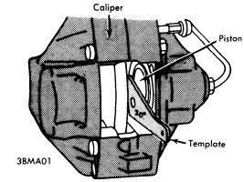
Reassembly - Coat all parts with ATE brake cylinder paste (or equivalent), reverse  disassembly procedure, and note the following: Use new seals, dust boots, and retaining rings when reassembling. When installing piston, make sure machined surface of piston face makes a 20° angle to wall of caliper bore (see illustration). Install disc pads after caliper has been installed on vehicle.
REAR WHEEL CYLINDER
Disassembly - Thoroughly clean outside of cylinder. Remove end caps, piston and seal assemblies, and spring. Remove dust cap and bleeder screw.
AUDI MASTER CYLINDER
(COMPONENT PARTS)
Cleaning & Inspection - Clean all parts in alcohol only. Check all parts for rust, corrosion, and damage. Check cylinder bore and piston for wear or damage. Cylinder bore should not exceed .6287" (16.00 mm) and piston diameter should not be less than .619" (15.74 mm). NOTE - Manufacturer recommends replacing rubber components on each disassembly.
Reassembly - Reverse disassembly procedure and not the following: Apply a thin coat of ATE brake cylinder paste (or equivalent) to all parts during assembly.
MASTER CYLINDER
Disassembly - Remove reservoir, brake light switch, circlip and dismantle cylinder. To extract piston, unscrew stop screw.
Cleaning & Inspecting - Clean all parts in denatured alcohol. Inspect bore and piston for rust or wear and replace any parts out of tolerance. It is advisable to always replace rubber parts.
Reassembly - Preassemble pistons and coat cups with ATE brake cylinder paste (or equivalent). Insert assembly into cylinder bore, install stop screw and circlip. Install brake light switch and resrevoir.
NOTE - Models without power brake servo differ slightly. Primary piston desgin is somewhat varied. Piston is equipped with only on secondary boot. There is no air compensating bore. Brake light switch location is different.


Read More..

BMW 1969 73 6 Cylinder Models Brake Repair Manual

| 0 comments |
Models Covered

  • 2500 (1969-70)
  • 2800 (1969-70)
  • 2800 CS & CSA (1969-71)
  • 3.0 CS & CSA (1969-71)
  • Bavaria (1972-73)


DESCRIPTION
Models 2800 CS and CSA use ATE four-piston fixed caliper disc brakes on front and leading-trailing shoe drum brake on the rear. All other models use four wheel ATE disc brakes with four-piston caliper on front and two-piston caliper on the rear. All models use twin circuit, tandem piston master cylinders. Four wheel disc brake system use a pressure limiter to control hydraulic pressure applied to rear brakes. Hydraulic pressure to rear brakes is adjustable with the pressure limiter. Hand brake actuates cable to rear brake shoes. A special duo-servo drum-disc combination is used on rear wheels with disc brakes.
ADJUSTMENT
DRUM BRAKES 
2800 CS & CSA - Release handbrake, hoist vehicle and using suitable wrench (6038) loosen each brake shoe with its eccentric adjusting screw. While revolving wheel, turn left adjusting screw counterclockwise and right screw clockwise, until wheel will no longer turn. Loosen each screw ⅛ turn at a time until wheel turns freely.
DISC PADS
Front and rear disc brake assemblies are self-adjusting, therefore, no adjustment in service is required.
PARKING BRAKE
PISTON ALIGNMENT
Disc Brakes (With Integral Drum On Rear) - Release parking brake lever, raise and support vehicle and remove rear wheels. Insert brake adjusting tool through .6" hole in rotor. Turn start wheel adjuster until rotor can no longer be turned, then back off adjuster two or three teeth. Working inside driver compartment, tighten adjustment nut on hand lever until parking brake holds vehicle (before fifth ratchet stop is reached).
Models With Rear Drum Brakes - Drum brakes must be adjusted before attempting to adjust handbrake. Handbrake should be adjusted if hand operated lever can be pulled up more than five notches. Adjust with handbrake lever completely disengage, by turning adjuster on cable and next to hand brake lever. Adjustment is correct when handbrake will lock rear wheels without passing through more than four or five notches on ratchet.
HYDRAULIC SYSTEM BLEEDING
NOTE - Manufacturer recommends replacing brake fluid entire system once a year to avoid moisture build-up. Attach a pressure bleeder to master cylinder reservoir. CAUTION - Do not exceed 29 psi. Raise and support vehicle and remove wheels. Attach a bleeder hose to bleeder screw, and immerse opposite end of hose into a container partially filled with brake fluid. Open bleeder screw, allow all air has been expelled  from system. NOTE - On front wheel four piston calipers, bleed lower inboard screw before bleeding lower outboard screw.
REMOVAL AND INSTALLATION
DRUM BRAKE SHOES
Removal - Hoist vehicle, remove rear wheels and brake drums. Detach brake shoes from bottom support, then pull shoes out of wheel cylinders. Disconnect hand brake cable from rear shoes. Separate shoes by removing return springs.
Installation - Reverse removal procedure and note the following: Install long end of shoe push rod spring toward handbrake lever. Adjust brakes.
DISC PADS
Removal - Raise and support vehicle and remove wheels. Drive out retaining pins toward inside of vehicle and remove cross spring. Using a suitable extractor tool (3.9314-14002), remove disc pads from caliper assembly.
Installation - 1) NOTE -  Replacement of disc pads should be done in complete sets only. Using a cylinder brush, clean guide surface and support surface in caliper. Siphon sufficient fluid from outer cylinder reservoir to prevent overflowing, then press pistons to bottom of bores.
2) On rear two piston calipers, ensure machines position of piston face makes a 20° angle to lower caliper wall. Install disc pads, cross spring and retaining pins. After installation, depress brake pedal several times to position pads against rotor.
CALIPER ASSEMBLY
Removal - Remove master cylinder reservoir cap and plug fluid outlet lines. Raise and support vehicle and remove tire and wheel assembly. Disconnect hydraulic line(s), remove caliper mounting bolts, and separate caliper from caliper from backing plate.
Installation - Reverse removal procedure and bleed hydraulic system.
ROTOR
Removal & Installation (Front) - With caliper assembly removed, remove hub grease cap, cotter pin, and nut. Remove hub and rotor assembly. Remove Allen head bolts retaining rotor to hub and remove rotor. To install, reverse removal procedure, tighten all bolts and fittings evenly, and bleed hydraulic system if necessary. Adjust front wheel bearing. See Wheel Bearing Adjustment in WHEEL ALIGNMENT Section.
Removal & Installation (Rear) - Remove rear wheel and caliper assembly, then pull rotor out from axle shaft flange. To install, reverse removal procedure, tighten all bolts and fittings evenly, and bleed hydraulic system if necessary.
PARKING BRAKE SHOES
Removal - With rear caliper and rotor removed, disconnect lower return spring using brake spring pliers. Turn retaining springs 90 degrees using suitable tool (7014) and remove. Pull brake shoes apart at bottom and lift away upwards.
Installation - Reverse removal procedure and adjust parking brake shoes and cables.
MASTER CYLINDER
Removal - Remove master cylinder reservoir cap and plug fluid outlet lines. Remove hose fittings from master cylinder and raise above reservoir fluid level. Mark hydraulic lines for reassembly reference and disconnect from master cylinder. Remove nuts attaching cylinder to power unit, and separate master cylinder from power brake unit.
POWER UNIT PUSH ROD ADJUSTMENTS

Installation - Reverse removal procedure and note the following: Make sure rubber "O" ring seal between master cylinder and power unit is not damaged. Check clearance between power unit thrust rod and master cylinder piston with Plastigage and, if necessary, set to .020" by inserting a shim behind plunger head. Bleed hydraulic system and check for fluid leaks.
POWER BRAKE UNIT
Removal - 1) Remove air cleaner and battery, disconnect oil reservoir for power steering (if equipped) and move to one side. Block brake fluid reservoir outlets and remove hoses from master cylinder.
2) Remove lower left instrument panel housing and secure to one  side. Remove brake pedal clevis pin, and disconnect vacuum hose from intake manifold. Remove hydraulic lines from master cylinder marking positions for reassembly reference. Remove nuts retaining power unit to support and remove power unit.
Installation - Reverse removal procedure, bleed hydraulic system, and check following adjustments: Adjust length of piston rod (A) to 14.49-14.53". Adjust pedal height (B) to 9.65". Adjust exposed depth of brake light switch plunger (C) to .24-.28". See illustration.
Check Valve Replacement - Check valve is located in power unit vacuum line at intake manifold. To remove, loosen hose clamps, remove vacuum hoses, and remove valve. To install, reverse removal procedure, making sure arrow or block portion of valve faces intake manifold.
Filter Replacement - With power brake unit removed from vehicle, pull back rubber dust boot and remove retaining ring. Remove silencer and filter. To install, reverse removal procedure.
REAR BRAKE PRESSURE LIMITER
Removal & Installation - Plug fluid outlets in brake fluid reservoir. Disconnect brake hose and rear brake lines from pressure limiter. Remove mounting bolts and pressure limiter. To install, reverse removal procedure and bleed hydraulic system.
OVERHAUL
DRUM BRAKE WHEEL CYLINDER
Disassembly - With wheel brake drum removed, back off shoe adjusting cams, disconnect brake line and remove cylinder from backing plate. Disassemble wheel cylinder and pay particular attention to location and direction of parts.
Cleaning & Inspection - Clean all parts in alcohol or other suitable non oil base solvent. Discard all rubber parts and inspect all other parts for wear or damage.
Reassembly - Dip new parts in clean brake fluid or apply ATE cylinder paste. To install cylinder, reverse disassembly procedure and bleed brakes.
BRAKE CALIPER
Disassembly - With caliper removed from vehicle and disc pads remove from caliper, remove clamping rings and rubber protecting caps. Hold one piston in place using a suitable clamp, insert a piece of wood in caliper  cavity, then apply compressed air to fluid inlet and remove opposite piston. Remove sealing ring using a suitable plastic tool. Remove remaining piston(s) and seal(s) in same manner. NOTE - DO NOT separate caliper halves unless a leak is detected. To disassemble, remove expansion bolts, separate caliper halves and remove sealing rings.
Cleaning & Inspection - Clean all parts in alcohol and check for wear or damage; replace parts as necessary.
Reassembly - Reassemble caliper (if separated) using new seals and expansion bolts. Tighten expansion bolts from inside out. Coat pistons and caliper bores with ATE brake cylinder paste (or equivalent), install sealing rings, then install pistons into bores. Make sure pistons are not tilted when inserting. On two pison calipers, make sure machined surface of piston face makes a 20 degree angle to lower caliper wall. Install rubber protecting caps and clamp rings.
MASTER CYLINDER
Disassembly - Push in on primary piston and remove secondary piston stop screw. Remove snap ring from end of cylinder and remove primary and secondary piston assemblies and return spring. Disassemble piston assemblies noting number of parts used.
Cleaning & Inspection - Clean all parts in alcohol and inspect for wear or damage. NOTE - Cylinders with surface defects in bores must be replaced; do not overhaul.
Reassembly - Reassemble piston assemblies using a thin coating of ATE brake cylinder paste (or equivalent). Install piston assemblies into cylinder bore using a suitable guide sleeve (BMW 6063) to prevent damaging seals. Install secondary piston stop screw, making sure that piston is pushed fully forward before screw is installed and tightened. Install retaining ring in end of master cylinder bore.

Read More..

Audi 100LS 1977 Brake Repair Guide

| 0 comments |
DESCRIPTION
Brake system is hydraulically operated, utilizing a tandem master cylinder and power brake unit. Front disc brakes consist of rotors attached to wheel hub and drive shaft and two piston calipers attached to strut assembly. Disc pads are equipped with a ceramic transmitter-type wear sensor. Transmitter is mounted on cross spring and will break when contact is made with pad plates, interrupting control circuit and causing indicator light on instrument panel to be activated. All models are equipped with pressure regulator that is mounted to body and operated by a spring connected to rear axle. Rear brakes are leading-trailing shoe/drum type, using a dual piston wheel cylinder. Parking brake is cable actuated, operating secondary shoes of rear brake assemblies.
ADJUSTMENT
NOTE - Adjustments or readjustments should be carried out on cold brakes. However, brakes must be warm when testing. Instrument panel trim must be removed to adjust master cylinder push rod free play.
MASTER CYLINDER PUSH ROD FREE PLAY
Adjustment of piston rod play at master cylinder is made by loosening lock nut and turning piston rod until correct free play, measured at brake pedal, is obtained. When correct free play of .039" is obtained between push rod and piston, free play is measured at brake pedal will be approximately .2".
FRONT DISC BRAKES
Front disc brakes are self-adjusting, therefore, no adjustment in service is required.
REAR DRUM BRAKES
Raise and support rear of vehicle and release parking brake. Using a 17 mm wrench, tighten eccentric adjusters until wheels can no longer be turned by hand. Loosen eccentric adjusters until wheels are just fee to turn.
PARKING BRAKE
NOTE - Because of the residual pressure in brake regulator, the right rear brake shoes might not fully release from drum. Before adjustment, move lever on pressure regulator rearward.
Raise and support rear of vehicle and adjust rear brakes. Lift parking brake lever until it engages third ratchet stop. Adjust nut at equalizer until rear wheels are just free to turn. When parking brake lever is pulled up one additional notch (to fourth ratchet stop), rear wheels should be locked.
BRAKE PRESSURE REGULATOR
Fig. 1 Brake Pressure Regulator Adjustment Points
Checking & Adjusting - 1) Rock vehicle back and forth several times, then measure distance from top of rim to bottom of fender lip. Measurement must be made with trunk empty, gas tank full, and driver in vehicle
2) Raise vehicle on a hoist and make measurement again. If there is a difference in measurements, adjust by turning clamps. See Fig. 1.
3) Connect pressure gauges to left front and right rear wheels. Bleed pressure gauges. Apply pressure to foot pedal and note reading at gauge. Repeat procedure on right and left rear wheels.
                        Brake Pressure Values
Application                                    Pressure (psi)
Left Front.............................................  700
Right Rear............................................. 475-625
Right Front............................................ 1400
Left Rear............................................... 765-945
NOTE - DO NOT adjust brake pressure regulator when pressure is applied to brake pedal.
4) If pressure at rear wheels is to high, release spring and move spring support arm forward. If pressure at rear wheels is too low, move support arm rearward.
HYDRAULIC SYSTEM BLEEDING
Fill master cylinder reservoir with brake fluid and maintain level throughout bleeding operation. Attach a hose to bleeder screw, and immerse opposite end in a container partially full of brake fluid. Open bleeder screw, approximately one-half turn, depress brake pedal, close bleeder screw, and slowly return pedal. Continue operation until air bubbles are no longer seen in discharged fluid. Bleeding sequence is left-rear, right-rear, right-front, left-front.
REMOVAL & INSTALLATION
FRONT DISC BRAKE PADS
Removal - Remove lock clips. Pull out retaining pins so they project into openings in side members. NOTE - Do not remove rubber grammets from side member holes. Using a suitable extractor tool (SB-3), remove disc pads from caliper.
NOTE - Disc pads can be removed on right side only after removing front exhaust pipe.
Installation - Press both pistons into caliper bores.
NOTE - Fluid level in master cylinder reservoir will rise. Siphon sufficient fluid to prevent reservoir from overflowing. Ensure pistons are in correct alignment in bores using suitable tool (B-5). Install disc pads in recesses of caliper, slide in retaining pins, and install lock clip. Pump brake pedal several times to position disc pads. Bleed hydraulic system if necessary.
Fig. 2 Audi 100LS Rear Brake Assembly
FRONT DISC BRAKE CALIPER
Removal - With wheel and tire removed, take out disc pads. Disconnect hydraulic line from caliper. Remove bolts securing caliper and take off caliper.
Installation - To install brake caliper, reverse removal procedure and bleed hydraulic system
FRONT DISC BRAKE ROTOR
Removal - With wheel and tire assembly removed, take off caliper. Do not disconnect hydraulic line unless necessary. Remove screw retaining rotor to wheel hub (if equipped) and withdraw rotor.
Installation - To install rotor assembly, reverse removal procedure and bleed hydraulic system.
REAR BRAKE DRUM
Removal - Raise and support vehicle, remove wheel and tire assembly. Pry off dust cap, remove cotter pin from hex nut, and remove nut. Remove brake drum making sure that retaining washer and wheel bearing do not fall out.
Installation - To install, reverse removal procedure, adjust brakes, and adjust wheel bearings. See Wheel Bearing Adjustment in WHEEL ALIGNMENT Section.
REAR BRAKE SHOES
Removal - With brake drum removed, remove retaining spring for brake shoes. Remove shoes as an assembly by disconnecting spring at bottom, pulling shoes back from wheel cylinder, and disconnecting parking brake cable.
Installation - To install, reverse removal procedure and note the following: Make sure long ends of retaining clip and spring are installed on secondary shoe and parking brake lever. Ensure brake shoes are correctly  positioned on wheel cylinder pistons.
REAR BRAKE WHEEL CYLINDER
Removal - With drum and shoes removed, depress pedal approximately 1.2" and hold in position using a suitable pedal support. Disconnect hydraulic line from rear of backing plate and plug line to prevent loss of fluid. Remove retaining screws and wheel cylinder.
Installation - To install, reverse removal procedure, adjust brakes and bleed hydraulic system.
MASTER CYLINDER
Removal - Disconnect hydraulic line at rear of master cylinder. Depress brake pedal 1.2-1.6" and hold in position using a suitable pedal support. Disconnect remaining hydraulic line and cylinder mounting nuts. Separate master cylinder from power unit taking care not to lose "O" ring installed betweend them.
Installation - To install, reverse removal procedure and bleed hydraulic system.
POWER BRAKE UNIT
Removal - Siphon brake fluid from master cylinder reservoir and disconnect hydraulic lines. Loosen hose clamp and disconnect vacuum hose from power unit. From inside vehicle remove trim below instrument panel as necessary. Disconnect push rod from brake pedal, remove power unit adapter attaching nuts, and remove power unit and master cylinder from engine compartment as an assembly. Separate master cylinder and adapter from power unit.
Installation - To install, reverse removal procedure and note the following: Be sure to install "O" ring between master cylinder and power unit. Install adaptor to power unit so that center punch mark on adaptor is located on lower right side facing engine. To complete installation, adjust pedal push rod free play and bleed hydraulic system.
Check Valve Replacement - A vacuum check valve is located in vacuum line between intake manifold and power unit. To remove, loosen hose clamps, separate vacuum hoses from check valve, and remove check valve. To install, reverse removal procedure and note the following: Check valve stamped with the word "MOTOR" and a arrow. End of  valve in which arrow points must be connected to shorter hose from intake manifold.
OVERHAUL
FRONT DISC BRAKE CALIPER
Fig. 3 Front Disc Brake Caliper Assembly
Disassembly - Remove disc pads. Pry out retaining ring and remove dust seal by hand. Place a small block of wood in caliper cavity, and remove piston by applying compressed air to fluid inlet. Remove remaining piston in same manner. Remove seal from caliper bore using a piece of wood or plastic. NOTE - Do not use hard or sharp tools for this purpose. Do not separate caliper halves.
Cleaning & Inspection - Clean all parts in alcohol only. Check cylinder bore and piston
 for damage. NOTE -  Do not machine caliper bore or piston. Parts are serviced by replacement only.
Fig. 4 Using a 20° Gauge to Position Caliper Piston
Reassembly - Coat all parts with ATE brake cylinder paste (or equivalent), reverse disassembly procedure, and note the following. Use new seals, dust boots, and retaining rings when reassembling. When installing piston, make sure machined surface of piston face makes a 20 degree angle to wall of caliper bore (see illustration). Install disc pads after caliper has been installed on vehicle.
REAR WHEEL CYLINDER
Disassembly - Thoroughly clean outside of cylinder. Remove end caps, piston and seal assemblies, and spring. Remove dust cap and bleeder screw.
Cleaning & Inspection - Clean all parts in alcohol only. Check all parts for rust, corrosion, or other damage. Check cylinder bore and piston for wear. Maximum allowable cylinder diameter is .6287; minimum allowable piston diameter .6197". Manufacturer recommends replacing rubber components each time cylinder is disassembled.
Reassembly - Reverse disassembly procedure and not the following: Apply a thin coat of ATE brake cylinder paste (or equivalent) to all parts during assembly.
MASTER CYLINDER
Disassembly - Thoroughly clean outside of master cylinder. Remove hydraulic fluid reservoir, remove retaining ring, and remove primary piston assembly. Loosen or remove (if necessary) piston stop screw and remove secondary piston assembly. Disassemble primary and secondary piston assemblies.
Cleaning & Inspection - Clean all parts in alcohol only. Dry all parts with compressed air and check that compensating parts of cylinder are free of obstructions. Check cylinder bore and pistons for rust, corrosion or other damage. Inspect cylinder bore and pinion for wear. Maximum allowable cylinder diameter is .817:; minimum allowable piston diameter is .807". Manufacturer recommends replacing all rubber parts whenever cylinder has been disassembled.
Reassembly - Reverse disassembly procedure and note the following: Do not apply grease to push rod as damage may result to rubber components.
POWER BRAKE UNIT
NOTE - Manufacturer does not recommend overhaul of power brake unit.
Fig. 5 Sectional View of Audi 100LS Tandem Master Cylinder


Read More..