Showing posts with label 77. Show all posts

Datsun F10 200SX B210 1976 77 Brake Repair Manual

| 0 comments |
DESCRIPTION
Brake system is hydraulically operated, utilizing a tandem master cylinder and a Master-Vac power brake unit. Front disc brakes consist of rotors attached to wheel hubs, and single cylinder, dual-piston, floating-calipers attached to steering knuckles. Rear brakes are leading-trailing shoe/drum type, using a single piston sliding wheel cylinder. Parking brake is cable actuated; operating wheel cylinders of rear brake assemblies.

ADJUSTMENT
PEDAL HEIGHT & FREE PLAY
F10 - Adjust pedal height to 6.8-7.0" (172-178 mm) by turning nut on master cylinder push rod. Adjust stop light switch so pedal just touches end of stop light switch; tighten lock nut. NOTE - Brake pedal should be checked for travel and smooth operation. Travel should be 5-5.25" (127-133 mm).
200SX - Adjust pedal height to about 6.9" (175.5 mm) using stop light switch. Lock switch in place with retaining nut. After pedal height is adjusted, loosen push rod lock nut and adjust pedal free play to .039-.118" (1-3 mm).
B210 - Adjust pedal height to specifications by moving stop lamp switch. Pedal height should be 6.14" (156 mm) on vehicles equipped with manual transmission and 6.22" (158 mm) on vehicles with automatic transmission. After pedal height is adjusted, loosen push rod lock nut and adjust pedal free play to .039-.197" (1-5 mm).
FRONT DISC BRAKE PADS
Front disc brakes are self-adjusting, therefore, no adjustment in service is required.
REAR BRAKE SHOES
F10 - Raise and support vehicle. Pump brake pedal several times to center brake shoes. Using a screwdriver, turn adjuster star until considerable drag is evident. Back off adjuster five or six notches and make sure drum rotates freely.
200SX - No adjustment required.
B210 - Raise and support vehicle. Using a suitable brake adjusting tool, tighten adjuster eccentric clockwise until brake shoe contacts drum. Return adjuster eccentric until shoe is slightly separated from drum. Check operation by turning drum and applying brakes; if shoe interferes with drum rotation, readjust.
PARKING BRAKE
With rear brakes properly adjusted, adjust parking brake cable turnbuckle until rear brakes are locked when parking brake lever is pulled to sixth or seventh ratchet stop. Release parking brake lever and ensure rear wheels turn freely and that all parts are returned to their original position.
COMBINATION VALVE
Function Test, All Models - Accelerate engine to 30 mph and rapidly apply brakes. If rear wheels lock before front wheels, malfunction of combination valve assembly (200SX & B210), or of separate proportioning valve (F10) is indicated.
Warning Light Operation & Reset, Except 200SX - 1) Instrument panel light will come on when a pressure difference of between 71-224 psi is evident between front and rear hydraulic systems. Combination valve  shuffle moves to side of low pressure and grounds electrical circuit, causing warning light to come on.
2) When hydraulic problem has been corrected and brakes have been bled, system should have 427 psi. Shuttle will then return to position and light will go out.
HYDRAULIC SYSTEM BLEEDING
Attach a bleed tube to bleeder screw and immerse opposite end of tube in a container partially filled with brake fluid. Pump brake pedal two or three times, keep pedal fully depressed, open bleeder screw and exhaust air, close bleeder screw, and return brake pedal. Repeat operation until air bubbles are no longer seen in discharged fluid. Repeat procedure on remaining brake lines. Bleed rear wheels first, then front wheels.

REMOVAL & INSTALLATION
FRONT DISC BRAKE PADS
Removal - Raise front of vehicle and support in place, then remove front wheels. Remove clips from retaining pins and pull out pins, coil springs and pad springs. Remove  pads from caliper assembly using a suitable pair of pliers.
Inspection - With friction pads removed, measure their thickness. Replace any pad that is worn to less than .063" (1.6 mm) in thickness (not including metal backing plate). It is recommended that friction pads be replaced as a set to prevent any possibility of uneven braking
NOTE - Replace all pads at same time.
Installation - Clean and apply P.B.C. grease (or equivalent) on yoke groove of cylinder body, sliding contact portions of yoke and end surface of piston. Loosen bleeder screw and push outer piston in cylinder until end surface of piston coincides with end surface of retaining ring on boot. Install inner brake pad. Push inner piston in cylinder by pulling on yoke, then install outer brake pad. After installing pads, depress brake pedal several times to seat pads.
FRONT DISC BRAKE CALIPER
Removal - Raise vehicle and suitable support on safety stands; remove tire and wheel. Remove brake friction pads as previously described. Disconnect brake line from wheel cylinder. To ease removal of caliper, remove strut assembly and knuckle arm mounting bolt. Withdraw caliper mounting bolt and separate it from strut assembly.
Installation - To install brake caliper assembly, reverse removal procedures, noting the following: Bleed hydraulic system.
FRONT DISC BRAKE ROTOR
Fig. 1 Exploded View of Datsun 200SX Rear
Brake Assembly
Removal - With caliper removed, remove hub dust cap, cotter pin and nut. Remove hub and rotor assembly with wheel bearing and washer in place. Remove bolts attaching rotor to wheel hub, and separate rotor from hub.
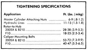
Installation - Reverse removal procedure, tighten rotor-to-hub bolts securely, and adjust wheel bearings. Use a dial indicator to measure rotor runout. Resurface rotor if runout exceeds .0047" (.12 mm) for 200SX & B210 or .006" (.15 mm) for F10.
REAR BRAKE ASSEMBLY
Removal (Rear) - Raise vehicle and suitable support on safety stands; remove tire and wheel. Loosen parking brake linkage at clevis pin and place out of way. Remove brake drum. Remove shoe retainer and return spring, then lift off shoe assembly. Disconnect brake line from wheel cylinder. If necessary, wheel cylinder can now be removed by taking out mounting bolt.
Inspecting - Inspect all brake components for damage or excessive wear and replace those found defective. Replace brake lining if it is oil soaked or lining is less than .059" (1.5 mm) thick.
Fig. 2 Exploded View of F10 and B210  Rear
Brake Assembly - 200SX Similar
Installation - To install rear brake lining, reverse removal procedures, noting the following:  Readjust shoe-to-drum clearance and, if necessary, bleed hydraulic system.
MASTER CYLINDER
Removal - Disconnect any electrical leads attached to cylinder reservoir. Disconnect front and rear brake lines from master cylinder outlet ports. On models equipped without power brakes, separate master cylinder push rod from pedal. Remove cylinder mounting nuts and slide unit off stud. Make sure brake fluid does not drop on point
NOTE - On F10 models, fluid reservoir can be removed attached to cylinder.
Installation - To install master cylinder, reverse removal procedures, noting the following: Bleed hydraulic system and check pedal height.
POWER BRAKE UNIT
Removal - Disconnect power unit push rod from brake pedal by removing clevis pin. Disconnect hydraulic lines from master cylinder and vacuum line from power unit, remove master cylinder attaching nuts, and remove master cylinder. Remove nuts attaching power unit to firewall, and remove power unit from engine compartment.
Installation - Reverse removal procedure, adjust brake pedal height, and bleed hydraulic system.
Check Valve Removal - Check valve is located in vacuum line between intake manifold and power unit on firewall. To remove, disconnect retaining clip from firewall, remove hose clamps, separate hoses from valve, and remove check valve. To install, reverse removal procedure.

OVERHAUL
Fig. 3 Exploded View of Front Disc Brake Caliper

FRONT DISC BRAKE CALIPER
Disassembly - With caliper removed, drain brake fluid and remove bleeder screw. Push both pistons into cylinder bore, then place yoke in a vise and tap the top of yoke lightly with a hammer to separate cylinder from yoke. Remove bias ring from outer piston, then remove retaining rings and boots. Push both pistons out in one direction. Remove piston seals from cylinder and yoke spring from yoke.
Inspecting - Thoroughly clean all internal parts and check each component fro excessive wear or damage. If caliper bore is damaged or excessively rusted, it must be replaced. If however, slight imperfections are evident, honing will eliminate them. It is recommended to replace all seals when overhauling.
Reassembly - Before assembling components, lightly coat with suitable brake grease. Insert bias ring into piston so round portion of ring fits to bottom of piston. Insert piston into cylinder. Do not fully seat piston. Install dust boot and retaining ring. Install yoke bias ring so it coincides with yoke groove of cylinder. Fit bias spring to yoke so bias spring faces bleeder side of cylinder. With yoke spring inserted in cylinder groove, properly align position of bias spring so groove of spring aligns with yoke. Assemble body-to-yoke, tapping lightly if necessary.
Fig. 4 Exploded View of Datsun Wheel Cylinder
Used on F10, 200SX and B210 Models
MASTER CYLINDER
NOTE - On F10 models, separate reservoir tank assembly.
Disassembly - Remove master cylinder reservoir caps and filters and drain brake fluid. Using a screwdriver, pry off stopper ring. Remove stopper screw and pull out primary piston assembly, spring and secondary piston assembly. Remove plugs and pull out front and rear check valves.
NOTE - On all except F10 models, do not remove reservoir tanks. If tanks are removed for any reason, discard and install new ones.
Inspecting - Thoroughly clean all components in approved grade brake fluid. Inspect all components for excessive wear or damage and replace parts as necessary.
Reassembly - Reverse disassembly procedure and note the following: Coat all parts with brake fluid (rubber parts with brake grease) when assembling.
Fig. 5 Exploded View of Datsun 200SX and B210
Master Cylinder - F10 Models Have Different
Reservoir Arrangement
POWER BRAKE UNIT
Disassembly - 1) Place power unit in a soft jaw vise with operating rod pointing up. Scribe an alignment mark on front and rear shell to assure reassembly in original position, then remove lock nut, clevis and dust boot from rear shell.
2) Place suitable wrench (ST08080000) over rear shell mounting studs. Press down on wrench while
rotating counterclockwise and remove rear shell, then lift out diaphragm plate assembly, diaphragm spring and push rod assembly. Pry off retainer and remove bearing and valve body seal assembly.
3) Remove diaphragm from diaphragm plate assembly, then pry off air silencer retainer and remove silencer and filter. Rotate diaphragm plate assembly until valve plunger key slot is down, then press in on plunger and shake out stop key. Remove reaction disc from plate assembly. Detach flange from front shell and remove front seal assembly.
Cleaning & Inspection - Clean all parts in denatured alcohol and blow dry with compressed air. Inspect front and rear shells for wear or damage. If slight rust is found on inside surface of shells, polish clean with fine emery cloth. Inspect all parts for cracks, nicks, distortion or other damage and replace as necessary.
Reassembly - Reverse disassembly procedure and note the following: Apply a thin coat of silicone grease to parts before installation. When assembling front shell to rear shell, ensure marks made during disassembly are aligned. After reassembly, measure distance from master cylinder mounting surface of power unit to end of power unit push rod; distance should be .38-.39" (9.8-10.0 mm). If distance is not to specifications, correct by adjusting end of push rod.


Fig. 6 Sectional View of Datsun Master Vac


Read More..

Arrow 1976 77 Drive Axles Repair Manual

| 0 comments |
Models Covered:

  • Arrow 
  • Colt
DESCRIPTION
Rear axle is of the banjo type, utilizing the removable carrier style differential. Light weight construction joins split tubular housing for each side with center covers welded to axle housing. Final drive is of the hypoid style. Axle shafts are semi-floating type supported with bearings at their respective ends in axle housing. Bearings are fitted to axles with pressure type bearing retainers. Pinion bearing preload, side bearing preload, and pinion depth adjustments are made with shims while differential side gears are adjusted with spacers.

REMOVAL AND INSTALLATION
Axle Shaft and Bearings
Removal - 1) Raise and suitable support rear axle housing so rear wheels clear ground. Remove rear wheel and brake back plate nuts, then disconnect wheel cylinder brake line. Fix suitable puller set (CT-1003 and C-637) to lug studs and work slide hammer until axle shaft is free to be withdrawn. Set brake back plate with parking brake attached out-of-way. Using suitable tool (C-637 with hook) remove axle shaft oil seal.
FIG. 1 MEASURING AXLE SHAFT
DEFLECTION
2) To remove axle bearing proceed as follows: Grind down bearing retainer at one point until retainer thickness is .04 - .06" (1.0 - 1.5 mm) then chisel ground portion and remove retainer. Using suitable bearing puller or press (CT-1120) remove bearing from axle.
3) Using a dial indicator, inspect axle shaft deflection in three spots (see illustration). Replace axle shaft if specifications are exceeded.
                                 Axle Shaft Deflection Table
Application                        Std. Value                           Service Limit
Point "A".............................  0-.004".................................   .004"
                                               (0-.10 mm)............................. (.10 mm)
Point "B"............................... 0-.002".................................   .002"
                                               (0-.05 mm)..............................(.05 mm)
Point "C"............................... 0-.08".....................................  .08"
FIG. 2 EXPLODED VIEW OF AXLE
SHAFT ASSEMBLY
                                               (0-2.0 mm)..............................(2.0 mm)
4) Rear axle bearing should be replaced when bearing noise is detected, when bearing axial play exceeds .014-.016" (.36-.41 mm) or if bearing axial free play exceeds .001-.002" (.03-.04 mm) at approximately 11 lbs. (5.0 kg) measuring force.
5) Inspect wheel hub bolts for tightness and bearing outer retainer for deformation, replace parts as necessary.

Installation - 1) Fit outer bearing retainer for sie against shaft splined end, then install bearing and inner bearing retainer. Seat bearing retainer with smaller chamfered side directed to the bearing. NOTE - Ensure bearing is completely seated.
2) Lightly coat lips at oil seal and using suitable oil seal installer (DT-10078 and CT-1008) fit axle shaftt oil seal in rear axle housing.
3) Using packing and shim in proper sequence, set clearance between bearing and outer bearing retainer to .00-.01" (.0-25 mm).
4) Carefully insert axle shaft assembly into axle housing using care not to damage seal. Slightly turn axle shaft until splines line up with differential side gears. Align packing oil holes with outer bearing retainer and tighten bearing retainer to axle housing flange. Connect brake line to wheel cylinder and bleed air from system.

DIFFERENTIAL CARRIER
FIG. 3 REMOVING DIFFERENTIAL
GEAR HOUSING
Removal - Drain oil from rear axle differential housing, then disconnect propeller shaft. Pull out both rear axle shafts approximately 2 1/2". Remove differential gear housing mounting nuts and withdraw the differential gear carrier. It may be necessary to top outside of housing to break gear carrier loose.
Installation - Lightly coat each bearing and gear with oil. Apply sealing compound on packing and axle housing seat, then assemble gear carrier to axle housing with nuts and tighten. Fill differential gear housing with .96 quart of suitable multi-purpose gear oil (API GL-5).

OVERHAUL
FIG. 5 REMOVING DRIVE PINION BEARING
Disassembly
Differential Gear Assembly - 1) Remove bearing carrier and lever gear case assembly form housing. Using suitable puller tool (C-293-P & C-293-39) pull differential side bearing. Keep right and left bearings and shim in sequence for reassembly.
2) Remove ring gear lock plate tabs and loosen bolts in diagonal sequence, then remove ring gear. Drive out pinion shaft lock pin from ring gear back side using a punch, pull out pinion shaft and pinion. Pinion side gears and spacers are now accessible. Note placement of pinion side gear and spacers and ensure they are reassembled in same position.
FIG. 6 REMOVING DRIVE PINION FRONT
BEARING OUTER RACE
Drive Pinion Assembly - 1) Hold end yoke with suitable tool (C-3281) and remove lock nut, then remove end yoke. Using a wheel puller, force out drive pinion with adjusting shim, rear inner bearing rce, spacer and preload adjusting shim.
2) With suitable bearing puller (C-293-P & C-293-39) remove rear bearing inner race and at the same time, pull off drive pinion adjusting shim. Using suitable drift, remove front drive pinion bearing outer race and oil seal. Repeat same procedure to remove bearing outer race.
INSPECTION
Check differential gears for correct tooth contact and replace gears if wear is excessive. Inspect bearing faces for roughness or score marks and replace, if necessary, bearing assembly. Ensure splines of side gears and rear axle shafts fit correctly. Check clearance between pinion gears and pinion shaft, if wear is excessive, replace components.
NOTE - To check gear tooth contact using pain impression method, refer to beginning of this section.
FIG. 7 EXPLODED VIEW OF COLT SEPARATE HOUSING REAR AXLE ASSEMBLY


FIG. 8 CHECKING DIFFERENTIAL PINION
AND SIDE GEAR BACKLASH
REASSEMBLY AND ADJUSTMENT
Case Assembly - 1) Install thrust washers (spacers) behind side gears in their original position and assemble pinion and side gears in differential. Insert both pinion gears, with pinion washers attached, so they mesh with side gears. It may be necessary to slightly rotate pinions to achieve desired meshing. Insert drive pinion shaft.
2) Check pinion and side gear backlash as shown in illustration, if backlash is beyond 0-.003" (0-.08 mm) adjust by selecting a side gear thrust washer (spacer) of correct size. If backlash is to be adjusted, ensure right and left sides are equally shimmed.
3) Thoroughly clean all dirt from ring gear mounting surface of differential case. Install bolts and lock washers. Tighten bolts alternately in a diagonal sequence and bend over lock tabs. Ensure lock washers are in contact with case rib after final torque has been performed.
Drive Pinion - Using a suitable drift and hammer or a press, seat front and rear bearing outer races into gear carrier ensuring that outer races do not cock. Ensure bearing races are completely seated before proceeding. Install shim between drive pinion and rear bearing. Using suitable bearing installer (CT-1075) press bearing onto drive pinion shaft. If drive pinion and bearings are scheduled to be reused, shims should be replaced with new ones of same thickness. In instances where the gear set is to be replaced, install new shims that are the same thickness as the used shims on drive pinion. NOTE - When determining the desired thickness of shim pack, amount of compression (sinkage) of shim pack and wear of the bearing (where old bearing is reused) must be taken into consideration.
Drive Pinion Depth - Install drive pinion spacer, front bearing, washer, end yoke and washer in order of removal. fit pinion shaft retaining nut and slowly tighten nut, continously checking, until pinion bearing preload is 6-9 INCH lbs. (7-10 cmkg) with oil seal not installed. Place suitable cylinder gauge on inside bearing pedestals of gear carrier housing. Place a block gauge on top end of drive pinion and slip a feeler gauge between the two gauges to obtain the correct clearance. The clearance between gauges should be .0118" (.300 mm). This is the standard height and any deviation from this height will be marked on the head of the pinion shaft and side of ring gear. To calculate the correct pinion height,  add or subtract the variation value from the standard height.
NOTE - Stamped values are in hundredth millimeters. Add or subtract the correct amount of shims as necessary.
Pinion Bearing Preload - This adjustment must be performed after the setting of the drive pinion depth. Remove end yoke and insert the bearing preload adjusting shim between pinion spacer and bearing, then tighten end yoke to 9-11 INCH lbs. (10-13 cmkg). In addition to the preload adjusting shims there are spacers available to provide proper adjustment. After finishing adjustment of drive pinion bearing preload remove the end yoke and apply a thin coat of grease to outer surface of oil seal, then drive seal into position in gear carrier. After greasing oil seal lip, insert end yoke and tighten nut.
FIG. 9 MEASURING CLEARANCE
BETWEEN SIDE BEARING AND GEAR CARRIER
Side Bearing Preload - Fit each side bearing into differential case leaving shims out; use suitable tool (CT-1102) for this procedure. Ensure side bearings are completely seated before proceeding. Install differential case assembly on gear carrier, then calculate the clearance bwetween side bearing outer race and gear carrier as shown in illustration. After obtaining clearance add .002" (.05 mm) preload figure to each side. Insert shims equally on both sides. Align gear carrier and bearing cap index marks, then tighten cap retaining bolts.
Ring Gear Deflection - Attach a dial indicator to back side of ring gear and measure deflection. If ring gear has excessive deflection, correct position of assembly in relation to differential case and again perform measurement. Replace ring gear or differential case as necessary.
Drive Pinion Backlash - Measure backlash of drive pinion in at least four different spots on ring gear with drive pinion securely fixed in final position. Set up a dial indicator on ring gear teeth edges. If measured backlash is greater than .005-.007" (.13-.18 mm), shift shims from ring gear side to back of the ring gear to obtain proper backlash. If the measure value is less than standard value, reverse the moving of shims as stated above. Side bearing shims are available in various thicknesses.
NOTE - Check gear tooth contact using point impression method described at beginning of this section.
Final Inspection and Assembly - Lightly coat each gear and bearing before and during reassembly with gear oil. After installing each component, ensure all rotating parts are free to move smoothly. Install differential gear assembly to axle housing after applying sealing agent and tighten gear carrier mounting nuts in diagonal sequence.
Read More..

Mercedes Benz 1975 77 Drive Axles Repair Guide

| 0 comments |
Models Covered:

  • 230
  • 240D
  • 280 Series
  • 300D
  • 450 Series
  • 6.9
DESCRIPTION
Axle assembly is of integral carrier housing, hypoid gear type in which centerline of drive pinion is mounted below centerline of ring gear. Removable rear housing cover permits inspection and service of differential. Some models may also be equipped with limited slip differential. All adjustments, except pinion bearing preload, are performed using shims. Pinion bearing preload is set using a collapsible spacer.
AXLE RATIO AND IDENTIFICATION
All of the above mentioned Mercedes Benz models use the integral carrier rear axle with semi-floating arm rear suspension. Some models also have limited slip differentials. To determine axle ratio, divide number of ring gear teeth by number of pinion gear teeth. Two different size center housing, generally used on smaller vehicles, has breather mounted on end cover and side covers are secured with six bolts. The large center housing, generally used on larger vehicles, has breather located on right side of housing and side covers are secured with eight bolts.
REMOVAL AND INSTALLATION
AXLE DRIVE SHAFTS
Fig. 1 Removing "C" Lock for Axle Shaft
Removal
Removal - 1) Drain lubricant from rear axle. Remove brake caliper and suspend on piece of wire. Remove bolt attaching axle drive shaft to axle shaft. Force axle drive shaft out of axle shaft. If required to aid axle drive shaft removal, loosen upper shock absorber mount and lower suspension arm to stop.
2) Support axle housing and remove rubber mount from body. Lower axle housing slightly. Clean housing and remove rear cover plate. Remove "C" lock holding axle drive shaft to differential side gear. Pull shaft from gear along with spacer ring.


Fig. 2 Exploded View of  Mercedes-Benz Drive Axle Assembly

Fig. 3 Checking Axle Shaft End Play
Installation - 1) Face of universal joint spider carries stamped "R" for right or "L" for left. Make sure correct axle is used on correct side. Place old spacer ring on inner constant velocity joint. Slide axle drive shaft into differential side gear and install new "C" lock into shaft. Check end play between inner universal joint and axle housing. There should be no perceptible end play. In addition lock ring should still turn in groove. If necessary, install a thicker or thinner lock ring to achieve desired results.
2) Completely telescope axle drive shaft and install axle shaft. Tighten securing nut. Mount end cover with suitable sealing compound and tighten bolts. Raise axle housing, install rubber mount and attach to body. Attach brake caliper using lock washer and fill axle with lubricant.
AXLE DRIVE SHAFT RUBBER SLEEVES
Removal - Remove axle drive shaft. Cut stop sleeve of constant velocity joint on beaded edge and pull sleeve from spider. Remove spider from hub along with six balls. Remove lock ring from groove in axle drive shaft and press spider from shaft. Pull stop sleeve and rubber sleeve from shaft. Loosen hose clamps and pull second rubber sleeve across disassembled end of axle drive shaft. Carefully clean joints and check balls and other parts for wear or damage.
Reassembly - 1) Slide new rubber sleeve on shaft up to bead. Place suitable assembly bushing (115 589 01 63 00) on splines to protect against damage. Place new stop sleeve on shaft and press spider on axle shaft. Install locking ring. Assemble universal spider and six balls using suitable magnetic ball holders (115 589 05 63 00) for assistance.
2) Place new sealing rings on universal spider and attach new protective sleeve. Insert complete drive axle into suitable beading tool (115 589 05 63 00) and install split supporting ring. Attach beading ring and bead edge of sleeve while tightening nuts against stop of beading tool. Remove axle from tool and fill constant velocity joint with 8.5 ozs. (250cc) of suitable C-V joint oil. Attach rubber sleeve on stop sleeve and on axle shaft with new hose clamps.
AXLE SHAFT AND BEARING
Removal - 1) Unscrew bolt and force axle drive shaft out of axle shaft, tie axle drive shaft up out of way. Do not allow axle dive shaft to hang freely. Remove brake caliper and rotor and if necessary, parking brake shoes. Using suitable wrench, remove slotted nut from axle shaft while holding shaft with suitable tool (136 589 05 31 00). Remove sealing rings from support housing using screwdriver.
2) Knock axle shaft out of support housing and remove bearing inner race along with spacer sleeve. Force outer sealing ring from support housing and pull outer bearing race out of outer bearing from wheel bearing. Knock outer bearing inner race from axle shaft.
Installation - 1) For identification, axle shafts have a stamped "R" for right or "L" for left. Insure that axle shafts are installed in correct sides. Press inner race of outer bearing onto axle shaft and install both bearing outer races in support housing. Coat seat for outer sealing ring on support housing with sealing compound and install seal making sure that seal rests straight against chamfer at bottom of housing. Fill cavity between two bearing race in support housing with 1.8 ozs. (50 grams) multi-purpose grease.
2) Attach new spacer sleeve to axle shaft and install into carrier housing. Attach bearing inner race for inner bearing to axle shaft. Fill new sealing ring between lips with anti-friction bearing grease and coat with sealing compound on outside diameter. Press bearing inner race and sealing compound on outside diameter. Press bearing inner race and sealing ring into housing. Install seal running ring and screw on new slotted nut.
3) Attach dial indicator holder to support housing and  check end play of axle shaft while tightening slotted nut and rotating axle shaft back and forth. End play should be .0016-.0024" (.04-.06 mm). If slot nut is overtightened, reducing end play to zero, install a new spacer sleeve and retighten slot nut. Lock slot nut by bending into grooves in axle shaft at two points. Install axle drive shaft, brake components and bleed brake system.
PINION FLANGE AND SEAL
Removal - 1) Remove exhaust system and shielding plate, if necessary. Loosen clamping nut and unscrew propeller shaft intermediate bearing from frame. One three-piece propeller shaft, loosen front clamping nut only. Unflange propeller shaft from axle and push forward out of centering alignment.
2) Make sure axle drive shafts are horizontal and that brakes are not dragging and check and record torque required to rotate entire rear axle assembly. Attach holding wrench to flange and loose slotted nut with suitable wrench (115 589 01 07 00). Pull flange from pinion using puller if required. Force seal out of housing using a screwdriver. Check running surface for seal on flange and replace flange if surface is worn.
Installation - 1) Coat new seal on outside diameter with sealing compound and knock in against stop in axle housing using suitable driver (116 589 12 61 00). Attach flange and carefully tighten slotted nut until turning torque for rear axle is equal to torque measured previously. Do not overtighten or a new collapsible spacer will have to be install on pinion.
2) Reconnect propeller shaft and lightly tighten propeller shaft intermediate bearing. Fill axle housing with oil, lower vehicle and move back and forth several times. Tighten clamping nut on universal and propeller shaft intermediate bearing. Reinstall shielding plate and exhaust system, if necessary.
AXLE ASSEMBLY
Removal - 1) Drain oil from rear axle. On vehicles without starting torque compensation, unscrew brake caliper at right and suspend out of way. On vehicles with starting torque compensation, disconnect brake cable control, unscrew holding bracket on support housing, remove rubber sleeve and push cover back. On all models, disconnect axle drive shafts from axle shaft on both sides and force drive shafts out of axle shafts.
2) If necessary, remove exhaust system and shielding plate. Loosen clamping nut and unscrew propeller shaft intermediate bearing on frame. On three-piece propeller shaft, loosen front clamping nut only. Disconnect propeller shaft and push forward out of way. Support axle assembly with jack and suitable holding fixture (115 589 35 63 00 for small center housing. 116 589 02 63 00 for large center housing).
3) Unscrew rear rubber mounting on frame floor, or unscrew socket bolt for rubber mounting on cover of axle housing. On 230 through 280 models, fold back rubber mat in trunk and remove rubber plugs. Unscrew axle housing from rear axle carrier. On all models, lower rear axle housing from rear axle carrier. On all models, lower rear axle and remove along with axle drive shafts. Use care not to let axle drive shafts droop. Unscrew rubber mounting from housing and replace if worn or damage.
Installation - 1) Attach rubber mounting to axle housing and place on jack and holding fixture. Move axle up under vehicle. Mount axle housing to rear axle carrier and tighten nuts. On 230 through 280 models, install rubber plugs and replace trunk floor mat. Install both axle drive shafts into axle shafts and tighten bolts.
2) Lift axle housing up to frame floor and attach rubber mounting to frame. Reconnect propeller shaft and lightly attach propeller shaft intermediate bearing. On vehicles without starting torque compensation, mount brake caliper using new lock washers. On vehicles with starting torque compensation, mount holding bracket for brake cable control to support housing, slide on cover and rubber sleeve, attach cable control and adjust parking brake.
Fig. 4 Removing Differential Assembly
from Housing
3) Fill axle with oil to level of filler hole, lower vehicle. Rock back and forth several times, then tighten clamping nut on propeller shaft and tighten propeller shaft intermediate bearing. Install exhaust system and shielding plate if removed.
OVERHAUL
DISASSEMBLY
1) Clamp axle housing in suitable support so that axle drive shafts are fully supported. Remove rear cover from housing and axle drive shafts from side gears (see "Axle Drive Shafts" under REMOVAL AND INSTALLATION). Remove bolts and push side bearing covers out of housing along with seal rings and shims, mark all parts for correct right and left side reassembly.
Fig. 5 Friction Disc Installation
Sequence
2) Tilt differential case slightly and remove from housing. Mark relative position of ring gear to differential case, remove bolts and carefully force gear from case. To disassemble case, pull roller bearings from case using suitable puller (187 589 05 33 00). Knock holding pin for pinion shaft out of case and remove pinion shaft.
3) On limited slip differentials, insert suitable assembly mandrels (116 589 18 61 00) through case and side gears. Remove pinions with spherical washers, then remove right side gear with friction discs, then repeat procedure for left side. On standard differentials, lift out side gears, thrust washers and spherical washers.
4) To remove drive pinion, remove flange nut and flange. Force pinion out of housing using tool (115 589 00 59 00). Pry seal out of housing with screwdriver. Screw suitable fixture (115 589 01 61 00) to housing and using suitable mandrel (115 589 01 61 06), press front bearing outer race out of housing. Now pull rear bearing outer race out of housing using suitable adapter (116 589 12 61 00 part 7 for small center housing or part 18 for large center housing). Press roller bearing inner race from pinion using suitable press plate (108 589 00 33 00).
Fig. 6 Zeroing Dial Indicator for Pinion Depth
Adjustment
REASSEMBLY AND ADJUSTMENT
Case Assembly (Standard Differential) - 1) Place thrust washers on side gears and insert in case. Insert assembly mandrels (116 589 18 61 00) into side gears and mount both pinions along with spherical washers. Insert dummy pinion shaft (115 589 03 61 00 for small center housing or 116 589 07 61 00 for large center housing) into case to locate pinion gears and spherical washers.
2) Check torque required to rotate side gears. Specified torque is 130-174 INCH lbs. (150-200 cmkg) with spot binding up to 304 INCH lbs. (350 cmkg) permitted with no end play. If necessary, change side gear thrust washers as necessary to achieve this torque value. When side gear preload is correct, insert pinion shaft in place of mandrel, install new clamping sleeve and press bearing inner races on case using suitable mandrel (115 589 04 61 00 for small center housing or 116 589 08 61 00 for large center housing).
Fig. 7 Reading Pinion Height
Case Assembly (Limited Slip Differential) - 1) Mount friction discs on side gears in correct sequence (see illustration). Install left side gear (ring gear side) with discs and insert assembly mandrel (116 589 18 61 00) through case, pinions and spherical washers. Check torque required to rotate side gears. Specified torque is 217-304 INCH lbs. (250-350 cmkg) with no end play. If necessary, change side gear thrust washers as necessary to achieve this torque value. When side gear preload is correct, insert pinion shaft in place of mandrel, install new clamping sleeve and press bearing inner races on case using suitable mandrel (116 589 08 61 00).
Drive Pinion Depth - 10 With dial indicator plunger device 116 589 00 23 00 depressed about .12" (3 mm) by gauge block 116 589 07 21 00 part 8 for small center housing or part 9 for large center housing, zero dial indicator. Press inner tapered roller bearing on drive pinion and place bearing outer race on roller cage of bearing. Insert pinion assembly into measuring device. On pinions from large center housings, place magnetic plate 116 589 01 21 00 part 4 on top of pinion. Place indicator stem on head of pinion or plate and note reading (example 1.50 mm).
Fig. 8 Zeroing Dial Indicator
NOTE - On all 450 Series, the height of the pinion gear head has been increased from 1.477" (37.5 mm) to 1.535" (39 mm). This must be considered when selecting pinion depth adjusting shims. This change was made as chassis and numbers: 0066963 (450 SLC); 017787 (450 SL); and 023515 (450 SE/SEL).
2) Now note adjustment value engraved on pinion shaft in tenths of millimeters (example: +20 = +.20 mm). From value measure above, add adjustment value if plus and subtract value if minus. (example: 1.50 + .20 = 1.70 mm). Insert gauge block holder into axle housing and screw on appropriate gauge block. Insert dial gauge holder 111 589 05 21 00 and zero indicator with stem depressed about .12" (3 mm).
3) Insert measuring device 115 589 00 21 00 part 3 for small center housing or 116 589 01 21 00 part 1 for large center housing together with dial gauge holder into right bore of housing and screw down. Read indicator reading difference between adjusting gauge and gauge block face end. If value is plus, it must be subtracted from result obtained in step 2) and if minus, must be added to above result (example: If measured deviation is +.16 mm, subtract this value from 1.70 mm to obtain 1.54 mm). This result is thickness of required shim.
Fig. 9 Measuring Housing Depth
4) Remove all tools from axle housing. Insert shim of calculated thickness into axle housing. If necessary, a thicker washer may be ground down to required thickness. Install outer races of bearings in housing using suitable installation tool (116 589 11 61 00). Lubricate bearing on drive pinion with hypoid gear oil and insert pinion and new collapsible spacer into hosing.
5) Install front bearing inner race using suitable tools. Coat new seal on circumference with sealing compound  and press into cover using suitable mandrel. Coat running surface of pinion flange with molybdenum disulphide paste and slide flange on drive pinion, making sure alignment marks are lined up.
Pinion Bearing Preload - 1) Check that runout of pinion flange does not exceed . 001" (.03 mm). If runout is excessive reposition flange on pinion until runout is to specification or replace flange. Attach suitable holding wrench (115 589 00 07 00) to flange and screw on new locking slot nut. Gradually tighten slot nut whil turning pinion and applying light hammer blows to axle housing. Continue tightening nut until torque required to rotate housing. Continue tightening nut until torque required to rotate pinion is 10.4-12.2 INCH lbs. (12-14 cmkg) with new bearings or 4.3-8.7 INCH lbs. (5-10 cmkg) with used bearings.
Fig. 10 Measuring Housing Spread
2) Use care not to exceed specified preload. If preload is exceeded, remove pinion from housing and replace collapsible spacer. Again insert measuring device together with dial gauge holder into right bore of housing and place magnetic measuring plate 116 589 01 21 00 part 4 on head of pinion. Dial indicator should read value engraved on pinion shaft. Maximum error is -.0008" (.02 mm). If error is higher, disassemble pinion and install correct shim.
Backlash & Side Bearing Preload - 1) On small center housing axles, press out sealing rings and outer bearing bores from side covers using suitable mandrel (115 589 00 35 00). On large center housing axles, remove sealing rings from side covers using suitable tool (115 589 00 35 00 part 5), then remove bearing outer race with suitable tool (116 589 00 35 00). On all axles, press in new outer races with suitable sleeve (116 589 04 43 00 part 5) and, on small center housing only disc (115 589 00 61 00 part 1).
Fig. 11 Measuring Ring-to-Gear Backlash
2) Coat new seals on outside diameter with sealing compound and press into bearing covers with suitable punch (116 589 05 43 00). Place previously used shims on bearing covers and install new sealing rings in grooves of covers. Carefully clean bore of ring gear and seat on differential case as ring gear is removed from case. Heat ring gear to about 140-158 Degrees F (60-70 degrees C) and install gear on case making sure installation marking are lined up if old ring gear and case is being used. If necessary, tap gear on case using rubber hammer. Tighten ring gear bolts uniformly and in a crosswise pattern.
3) Place differential case into housing. Place suitable assembly fixture (116 589 06 61 00) into housing. Place both bearing covers with shims on centering surface of fixture and slide into housing on same side from which they were removed. Turn both covers so that marking "bottom" ("unten") face downwards. Remove assembly fixture and screw in bearing cover bolts but do not tighten. Mount suitable case spread measuring device (115 589 04 21 00 for small center housing or 116 589 04 21 00 for large center housing) and support (115 589 04 21 00 part 3) on housing and zero dial indicator.
4) Tighten bolts on bearing covers, crosswise, to a torque of 14.5 ft. lbs. (2 mkg). Place spread measuring device on support blocks and measure spread of axle housing. Spread should be.004-.006" (.10-.15 mm) for small center housing or .006-.008" (.15-.20 mm) for large center housing. Adjust size of shims as necessary to achieve specified case spread. Install suitable backlash measuring device (115 589 03 23 00) into right side bearing bore and clamp down.
5) Measure backlash at four points on ring gear. The lowest measured value of backlash should be .003-.0055" (.08-.14 mm). Adjust shims from side to side as necessary to achieve specified backlash. When preload and backlash is correct, install both axle drive shafts with new "C" lock rings. Clean sealing surface on end cover and axle housing and coat with sealing compound. Install cover and tighten bolts.


Read More..