Showing posts with label BMW. Show all posts

BMW i3 The Intersection of Policy Business Carbon

| 0 comments |

I recently came across this interesting report. Its titled "BMW: i3 Electric Vehicle. The Intersection of Policy, Business, & Carbon" and was written by Lauren Blasch, Jeremy Pomp, Marla Stancil, Shyam Vijayaraghavan.


The report focuses on electric vehicles and their carbon footprint in general, as opposed to being i3 specific. It demonstrates that depending on the source of the electricity used for charging the car, EVs can range from better to worse than a Toyota Prius in carbon emissions. Its interesting that they used the most efficient hybrid currently available to compare electric vehicle emissions to. I think it might have been more useful to use the Pruis and also show on the graph the average internal combustion engine cars carbon emissions also. They even go as far as to detail which states are better suited for electric cars based on their electricity generation mix. The good news is that New York and California, the target markets for the i3 since they both have "megacities" were two of the states that were "EV favorable" The report is only 28 pages long and many of the pages are graphs so it doesnt take long to read. There are some interesting fact in there so I recommend reading it if you are interested in electric vehicles and their impact on the environment.

One thing to consider though, the report is strictly focused on the carbon emissions of vehicles and I advocate electric cars for more reasons than just their carbon footprint. Even if you live in a state that produces 100% of its electricity from burning coal, and by using an EV you are producing more carbon than if you owned a Toyota Prius, you are still spending your energy dollars on a DOMESTIC product. You are not contributing to the crushing trade imbalance, much of which is created from importing foreign oil and you are not sending some your money to radical Middle Eastern regimes, many of which hate us. Electricity is produced and distributed by local and regional companies, and 100% of the money you spend on it stays local. If you ask me, thats reason enough to drive an electric car.
Read More..

Three Cylinder in the BMW i8 will be built in England

| 0 comments |
The three-cylinder engine for the hybrid sports car, BMW will build i8 in his English factory at Hams Hall near Birmingham. This was known sales and marketing director Ian Robertson, London. The planned 2 +2 seating himself is said to be produced in 2014 in Leipzig.

2013 bmw i8

The drive of the BMW i8 consists of a 164 kW / 223 hp three-cylinder gasoline engine that drives the rear axle. It is coupled with an electric motor at the front, makes the 96 kW / 131 hp. The top speed of the vehicle is limited to 250 km / h. The standard average fuel consumption is said to be less than three liters per 100 kilometers. Up to 30 kilometers, the BMW i8-electric drive.

The BMW Plant Hams Hall currently produces engines for the Mini, the 1 Series and 3 Series and the X1.
Read More..

BMW 318i 1984 Electrical Troubleshooting Manual

| 0 comments |
Manufacturer: BMW
Mode: 318i
Year: 1983


Quick Reference Index:

  • Symbols
  • Systematic Troubleshooting
  • Diagnostic Connector
  • Power Distribution Box
  • Fuse Data
  • Power Distribution
  • Start/Ignition/ Fuel Delivery
  • Fuel Control
  • Idle Speed Control
  • Vacuum Advance
  • Charging System
  • Wiper/Washer
  • Speedometer/Indicators
  • Tachometer/Fuel Economy Gauge
  • Service Interval Indicator
  • Brake Warning System
  • Ignition Key Warning/Seatbelt Warning
  • Headlights (control)/Fog Lights (with one relay)
  • Headlights (power)
  • Lights: Turn/Hazard Warning
  • Lights: Front Park/ Front Side Marker/ Tail
  • Lights: Rear Marker License
  • Lights: Trunk Light
  • Back Up Lights
  • Stoplights
  • Horn
  • Interior Lights
  • Cigar Lighter/ Digital Clock/ Glove Box Light/ Auto Charging Flashlight
  • Rear Defogger
  • Radio/ Power Antenna
  • Power Mirrors
  • Headlights (control)/ Fog Lights (with two relays)
  • Headlights (power)/ Fog Lights (with two relays)
  • Dash Lights
  • Heating and Air Conditioner (compressor controls/fresh or recirculating air control/ water control)
  • Auxiliary Fan
  • Central Locking (control/request)
  • Power Windows
  • Ground Distribution (G101, G102, and G104/G200 Partial, G302 and G200)
  • Component Locations
File Size: 6.84 MB
File Type: PDF, ZIP
Read More..

BMW 525i 535i E34 1989 Electrical Troubleshooting manual

| 0 comments |
Manufacturer: BMW
Model: 525i/535i E34
Year:
**Production 2/89 and Later (All Vehicles Equipped with KL61 Relay)

Quick Reference Index:

  • Systematic Troubleshooting
  • Power Distribution Chart
  • Fuse Details
  • Ground Distribution
  • Diagnostic Link
  • Injection Electronics (DME 1.3)
  • Charging System
  • Start
  • E-Box Fan
  • Electronic Transmission Control (AEGS)
  • Supplemental Restraint System (SRS)
  • Power Assist Steering (Servotronic)
  • Anti Lock Braking System (ABS)
  • Power Mirrors
  • ZKE Door Lock Heating (TSH)
  • ZKE Central Locking (ZV)
  • ZKE Power Windows (FH)
  • Power Seats/ Sunroof/ Central Body Electronics/ Horn
  • Windshield Wiper Control and Pressure Control, Washer Jet heaters
  • Instrument Cluster/ Check Control
  • Light Switch Details
  • Lamp Monitor (LKM)
  • Headlights/ Fog Lights/ Turn/ Hazard Lights
  • Park/ Tail/ Underhood Lights/ License/ Trunk Lights/ Back Up Lights/ Brake Lights
  • Interior Lights/ Glove Box Light/ Cigar Lighter/ Charging Plug
  • Integrated Climate Regulation
  • Auxiliary Fan/ Radio/ CD Player (Provisions)
  • Cellular Telephone (Provisions)
  • Cruise Control (Tempomat)
  • On-Board Computer (BCIV)
  • Component Location Chart
  • Component Location Views
  • Splice Location Views
  • Connector Views
File Size: 8 MB
File Type: PDF, ZIP
Read More..

BMW M5 1988 Electrical Repair

| 0 comments |
Electrical Troubleshooting Manual, Schematic and Wiring Diagrams For:
Manufacturer: BMW
Models Covered: 535i and M5 E28 Series
Year: 1987 to 1988*
*1987 Vehicles built before 9/1986 use 1986 535i Electrical Troubleshooting manual for diagnostics


Quick Reference Index:

  • Power Distribution Box
  • Fuse Data
  • Diagnostic Connector
  • Start
  • Antilock Braking System (ABS)
  • Splice Location Views
  • Injection Electronics
  • Fuel Control/ Idle Speed Control
  • Ignition and Charging System
  • Engine Block Diagrams
  • Wiper/ Washer
  • Speedometer/ Gauges/ Warning Indicators
  • Active Check Control
  • Electronic Transmission Control
  • Brake Lining Warning
  • Ignition Key Warning Seatbelt Warning
  • Headlights/ Fog Lights/ Turn/ Hazard Warning
  • Front Park/ Front Maker/ Tail
  • Rear Marker/ License/ Trunk
  • Cruise Control/ Stop Lights
  • Dash Lights/ Interior Lights
  • A/C Temperature and Blower Controls
  • On-Board Computer
  • Back Up/ Transmission Range/ Heated Door Lock
  • Cigar Lighter/ Glove Box Light/ Digital Clock/ Auto-Charging Flashlight
  • Horn/ Sunroof/ Rear Defogger/ Power Windows/ Mirrors/ Central Locking (select)
  • Central Locking (control)/ Radio/ Power Antenna/ Auxiliary Fan/ Heater/ Air Conditioning
  • Ground Distribution/ Component Locations/ Notes
File Size: 15 MB
File Type: PDF, ZIP
Read More..

BMW 1969 73 6 Cylinder Models Brake Repair Manual

| 0 comments |
Models Covered

  • 2500 (1969-70)
  • 2800 (1969-70)
  • 2800 CS & CSA (1969-71)
  • 3.0 CS & CSA (1969-71)
  • Bavaria (1972-73)


DESCRIPTION
Models 2800 CS and CSA use ATE four-piston fixed caliper disc brakes on front and leading-trailing shoe drum brake on the rear. All other models use four wheel ATE disc brakes with four-piston caliper on front and two-piston caliper on the rear. All models use twin circuit, tandem piston master cylinders. Four wheel disc brake system use a pressure limiter to control hydraulic pressure applied to rear brakes. Hydraulic pressure to rear brakes is adjustable with the pressure limiter. Hand brake actuates cable to rear brake shoes. A special duo-servo drum-disc combination is used on rear wheels with disc brakes.
ADJUSTMENT
DRUM BRAKES 
2800 CS & CSA - Release handbrake, hoist vehicle and using suitable wrench (6038) loosen each brake shoe with its eccentric adjusting screw. While revolving wheel, turn left adjusting screw counterclockwise and right screw clockwise, until wheel will no longer turn. Loosen each screw ⅛ turn at a time until wheel turns freely.
DISC PADS
Front and rear disc brake assemblies are self-adjusting, therefore, no adjustment in service is required.
PARKING BRAKE
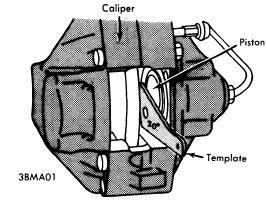
PISTON ALIGNMENT
Disc Brakes (With Integral Drum On Rear) - Release parking brake lever, raise and support vehicle and remove rear wheels. Insert brake adjusting tool through .6" hole in rotor. Turn start wheel adjuster until rotor can no longer be turned, then back off adjuster two or three teeth. Working inside driver compartment, tighten adjustment nut on hand lever until parking brake holds vehicle (before fifth ratchet stop is reached).
Models With Rear Drum Brakes - Drum brakes must be adjusted before attempting to adjust handbrake. Handbrake should be adjusted if hand operated lever can be pulled up more than five notches. Adjust with handbrake lever completely disengage, by turning adjuster on cable and next to hand brake lever. Adjustment is correct when handbrake will lock rear wheels without passing through more than four or five notches on ratchet.
HYDRAULIC SYSTEM BLEEDING
NOTE - Manufacturer recommends replacing brake fluid entire system once a year to avoid moisture build-up. Attach a pressure bleeder to master cylinder reservoir. CAUTION - Do not exceed 29 psi. Raise and support vehicle and remove wheels. Attach a bleeder hose to bleeder screw, and immerse opposite end of hose into a container partially filled with brake fluid. Open bleeder screw, allow all air has been expelled  from system. NOTE - On front wheel four piston calipers, bleed lower inboard screw before bleeding lower outboard screw.
REMOVAL AND INSTALLATION
DRUM BRAKE SHOES
Removal - Hoist vehicle, remove rear wheels and brake drums. Detach brake shoes from bottom support, then pull shoes out of wheel cylinders. Disconnect hand brake cable from rear shoes. Separate shoes by removing return springs.
Installation - Reverse removal procedure and note the following: Install long end of shoe push rod spring toward handbrake lever. Adjust brakes.
DISC PADS
Removal - Raise and support vehicle and remove wheels. Drive out retaining pins toward inside of vehicle and remove cross spring. Using a suitable extractor tool (3.9314-14002), remove disc pads from caliper assembly.
Installation - 1) NOTE -  Replacement of disc pads should be done in complete sets only. Using a cylinder brush, clean guide surface and support surface in caliper. Siphon sufficient fluid from outer cylinder reservoir to prevent overflowing, then press pistons to bottom of bores.
2) On rear two piston calipers, ensure machines position of piston face makes a 20° angle to lower caliper wall. Install disc pads, cross spring and retaining pins. After installation, depress brake pedal several times to position pads against rotor.
CALIPER ASSEMBLY
Removal - Remove master cylinder reservoir cap and plug fluid outlet lines. Raise and support vehicle and remove tire and wheel assembly. Disconnect hydraulic line(s), remove caliper mounting bolts, and separate caliper from caliper from backing plate.
Installation - Reverse removal procedure and bleed hydraulic system.
ROTOR
Removal & Installation (Front) - With caliper assembly removed, remove hub grease cap, cotter pin, and nut. Remove hub and rotor assembly. Remove Allen head bolts retaining rotor to hub and remove rotor. To install, reverse removal procedure, tighten all bolts and fittings evenly, and bleed hydraulic system if necessary. Adjust front wheel bearing. See Wheel Bearing Adjustment in WHEEL ALIGNMENT Section.
Removal & Installation (Rear) - Remove rear wheel and caliper assembly, then pull rotor out from axle shaft flange. To install, reverse removal procedure, tighten all bolts and fittings evenly, and bleed hydraulic system if necessary.
PARKING BRAKE SHOES
Removal - With rear caliper and rotor removed, disconnect lower return spring using brake spring pliers. Turn retaining springs 90 degrees using suitable tool (7014) and remove. Pull brake shoes apart at bottom and lift away upwards.
Installation - Reverse removal procedure and adjust parking brake shoes and cables.
MASTER CYLINDER
Removal - Remove master cylinder reservoir cap and plug fluid outlet lines. Remove hose fittings from master cylinder and raise above reservoir fluid level. Mark hydraulic lines for reassembly reference and disconnect from master cylinder. Remove nuts attaching cylinder to power unit, and separate master cylinder from power brake unit.
POWER UNIT PUSH ROD ADJUSTMENTS

Installation - Reverse removal procedure and note the following: Make sure rubber "O" ring seal between master cylinder and power unit is not damaged. Check clearance between power unit thrust rod and master cylinder piston with Plastigage and, if necessary, set to .020" by inserting a shim behind plunger head. Bleed hydraulic system and check for fluid leaks.
POWER BRAKE UNIT
Removal - 1) Remove air cleaner and battery, disconnect oil reservoir for power steering (if equipped) and move to one side. Block brake fluid reservoir outlets and remove hoses from master cylinder.
2) Remove lower left instrument panel housing and secure to one  side. Remove brake pedal clevis pin, and disconnect vacuum hose from intake manifold. Remove hydraulic lines from master cylinder marking positions for reassembly reference. Remove nuts retaining power unit to support and remove power unit.
Installation - Reverse removal procedure, bleed hydraulic system, and check following adjustments: Adjust length of piston rod (A) to 14.49-14.53". Adjust pedal height (B) to 9.65". Adjust exposed depth of brake light switch plunger (C) to .24-.28". See illustration.
Check Valve Replacement - Check valve is located in power unit vacuum line at intake manifold. To remove, loosen hose clamps, remove vacuum hoses, and remove valve. To install, reverse removal procedure, making sure arrow or block portion of valve faces intake manifold.
Filter Replacement - With power brake unit removed from vehicle, pull back rubber dust boot and remove retaining ring. Remove silencer and filter. To install, reverse removal procedure.
REAR BRAKE PRESSURE LIMITER
Removal & Installation - Plug fluid outlets in brake fluid reservoir. Disconnect brake hose and rear brake lines from pressure limiter. Remove mounting bolts and pressure limiter. To install, reverse removal procedure and bleed hydraulic system.
OVERHAUL
DRUM BRAKE WHEEL CYLINDER
Disassembly - With wheel brake drum removed, back off shoe adjusting cams, disconnect brake line and remove cylinder from backing plate. Disassemble wheel cylinder and pay particular attention to location and direction of parts.
Cleaning & Inspection - Clean all parts in alcohol or other suitable non oil base solvent. Discard all rubber parts and inspect all other parts for wear or damage.
Reassembly - Dip new parts in clean brake fluid or apply ATE cylinder paste. To install cylinder, reverse disassembly procedure and bleed brakes.
BRAKE CALIPER
Disassembly - With caliper removed from vehicle and disc pads remove from caliper, remove clamping rings and rubber protecting caps. Hold one piston in place using a suitable clamp, insert a piece of wood in caliper  cavity, then apply compressed air to fluid inlet and remove opposite piston. Remove sealing ring using a suitable plastic tool. Remove remaining piston(s) and seal(s) in same manner. NOTE - DO NOT separate caliper halves unless a leak is detected. To disassemble, remove expansion bolts, separate caliper halves and remove sealing rings.
Cleaning & Inspection - Clean all parts in alcohol and check for wear or damage; replace parts as necessary.
Reassembly - Reassemble caliper (if separated) using new seals and expansion bolts. Tighten expansion bolts from inside out. Coat pistons and caliper bores with ATE brake cylinder paste (or equivalent), install sealing rings, then install pistons into bores. Make sure pistons are not tilted when inserting. On two pison calipers, make sure machined surface of piston face makes a 20 degree angle to lower caliper wall. Install rubber protecting caps and clamp rings.
MASTER CYLINDER
Disassembly - Push in on primary piston and remove secondary piston stop screw. Remove snap ring from end of cylinder and remove primary and secondary piston assemblies and return spring. Disassemble piston assemblies noting number of parts used.
Cleaning & Inspection - Clean all parts in alcohol and inspect for wear or damage. NOTE - Cylinders with surface defects in bores must be replaced; do not overhaul.
Reassembly - Reassemble piston assemblies using a thin coating of ATE brake cylinder paste (or equivalent). Install piston assemblies into cylinder bore using a suitable guide sleeve (BMW 6063) to prevent damaging seals. Install secondary piston stop screw, making sure that piston is pushed fully forward before screw is installed and tightened. Install retaining ring in end of master cylinder bore.

Read More..

BMW 318ti 1999 Electrical Repair

| 0 comments |
Electrical Troubleshooting Manual, Schematics and Wiring Diagrams For:
Manufacturer: BMW
Model: 318ti E36/5
Year: 1999 (Vehicles Produced 9/1998 thru 08/1999


Quick Reference Index:

  • Introduction/ Symbols
  • Power Distribution and Fuse Chart
  • Fuse Details, Ground Distribution
  • Data Link
  • Engine Control System (DME M5.2, 4-Cylinder M44)
  • Start and Charging System
  • Electronic Transmission Control (EGS A4S 270R)
  • Supplemental Restraint System (Airbag)
  • Slip Control (ABS)
  • Power Mirrors
  • ZKE: Door Lock Heating (TSH), Central Locking (ZV), Power Windows (FH)
  • Power Seats and Lumbar Support. Heated Seats
  • Power Sunroof (SHD), Central Body Electronics (ZKE IV)
  • Horn, Drive-Away Protection (EWS II)
  • Wiper/ Washer Module  (WWM)
  • Headlight Washer (SRA)
  • Windshield Washer Jet Heaters, Heating Control
  • Instrument Cluster, Clock, Light Switch Details Headlights, Fog Lights
  • Turn/ Hazard Lights/ Park/ Tail/ Underhood Lights
  • License Plate/ Luggage Compartment Lights
  • Back up Lights, Brake Lights, Interior Lights, Interior Accessories, Crash Control Module
  • Rear Window Defogger, Integrated Heating-Climate Control
  • Radio/ CD Player (Provisions)/ HIFI
  • Cellular Telephone (Provisions)
  • Cruse Control (Tempomat), Anti-theft System (ALPINE)
  • Board Computer (BC-LOW)
  • Component Location Chart and Views
  • Splice Location Views, Connector Views
File Size: 2 MB
File Type: PDF, ZIP
Read More..

BMW 325e 318i 1984 Electrical Troubleshooting Manual

| 0 comments |
Manufacturer: BMW
Model: 325e / 318i 
Year: 1984


Quick Reference Index:

  • Symbols
  • Systematic Troubleshooting
  • Diagnostic Connector
  • Power Distribution Box
  • Fuse Data
  • Power Distribution
  • Start/Ignition/ Fuel Delivery
  • Fuel Control
  • Idle Speed Control
  • Vacuum Advance
  • Charging System
  • Wiper/Washer
  • Speedometer/Indicators
  • Tachometer/Fuel Economy Gauge
  • Service Interval Indicator
  • Brake Warning System
  • Ignition Key Warning/Seatbelt Warning
  • Headlights (control)/Fog Lights (with one relay)
  • Headlights (power)
  • Lights: Turn/Hazard Warning, Front Park/ Front Side Marker/ Tail/ Rear Marker License/ Trunk Light
  • Back Up Lights, Stoplights, Horn, Interior Lights
  • Cigar Lighter/ Digital Clock/ Glove Box Light/ Auto Charging Flashlight
  • Rear Defogger
  • Radio/ Power Antenna
  • Power Mirrors
  • Headlights (control and power)/ Fog Lights (with two relays)
  • Dash Lights
  • Heating and Air Conditioner (compressor controls/fresh or recirculating air control/ water control)
  • Auxiliary Fan
  • Central Locking (control/request)
  • Power Windows
  • Ground Distribution (G101, G102, and G104/G200 Partial, G302 and G200)
  • Component Locations
File Size: 11.63 MB
File Type: PDF, ZIP
Read More..

BMW 635CSi 1985 Electrical Repair

| 0 comments |
Electrical Troubleshooting Manual, Schematics and Wiring Diagrams For:
Manufacturer: BMW
Model: 635CSi E24
Year: 1985


Quick Reference Index:

  • Power Distribution Box
  • Fuse Data
  • Diagnostic Connector
  • Start
  • Fuel Delivery/ Evaporative Control
  • Fuel Control/ Idle Speed Control
  • Ignition and Charging System
  • Wiper/ Washer
  • Speedometer/ Gauges/ Warning Indicators
  • Active Check Control
  • Brake Lining Warning
  • Ignition Key Warning Seatbelt Warning
  • Headlights/ Fog Lights/ Turn/ Hazard Warning
  • Front Park/ Front Maker/ Tail
  • Rear Marker/ License/ Trunk
  • Cruise Control/ Stop Lights
  • Dash Lights/ Interior Lights/ Dash/ Transmission Range
  • Back Up/ Transmission Range
  • Cigar Lighter/ Glove Box Light/ Digital Clock/ Auto-Charging Flashlight
  • Horn/ Sunroof/ Rear Defogger/ Power Windows/ Mirrors/ Central Locking (select)
  • Central Locking (control)/ Radio/ Power Antenna/ Auxiliary Fan/ Heater/ Air Conditioning
  • Ground Distribution/ Component Locations/ Notes/ Windshield Wipers Jet Heaters
  • Splice Locations (Front, Middle, Engine, Rear Harnesses) 
File Size: 9 MB
File Type: PDF, ZIP
Read More..

BMW 5 Series Service Manual

| 0 comments |
Manufacturer: BMW
Model: 5-Series 525i, 530i, 535i, 540i, including touring, 
Year: 1989, 1990, 1991, 1992, 1993, 1994, 1995


Quick Reference Index:

  • General Data and Maintenance
  • Engine
    Engine-General, Engine Removal and Installation, Cylinder Head Removal and Installation, Cylinder Head and Valvetrain, Camshaft Timing Chain, Camshaft Timing Belt, Lubrication System, Ignition System--DME, Battery, Starter, Alternator, Fuel Injection--DME, Fuel Tank and Fuel Pump, Radiator and Cooling System, Exhaust System
  • Transmission
    Transmission-General, Clutch, Manual Transmission, Automatic Transmission, Gearshift Linkage, Driveshaft
  • Suspension, Steering and Brakes
    Suspension, Steering and Brakes - General, Front Suspension, Steering and Wheel Alignment, Rear Suspension, Final Drive, Brakes
  • Body
    Body-General, Fenders and Engine Hood, Doors, Trunklid, Tailgate
  • Body Equipment 
    Exterior Trim Bumpers, Door Windows, Interior Trim, Central Locking, Seats, Sunroof
  • Electrical System
    Electrical System - General, Fuses and Relays, Wipers and Washers, Switches and Electrical Accessories, Instruments, Exterior Lighting, Heating and Air Conditioning, Radio
  • Equipment and Accessories
    Seat Belts, Air Bag System (SRS)
  • Electrical Wiring Diagrams
File Size: 61 MB
File Type: PDF, ZIP
Read More..

BMW 850i 1991 Electrical Repair

| 0 comments |
Electrical Troubleshooting Manual, Schematics and Wiring Diagrams For
Manufacturer: BMW
Model: 850i E31
Year: 1991


Quick Reference Index:

  • Introduction/ Symbols
  • Power Distribution and Fuse Chart
  • Fuse Details, Ground Distribution
  • Data Link
  • Engine Control System (DMEM1.7, 12-Cylinder M70)
  • Electronic Throttle Control System (EML 12-Cylinder)
  • Start and Charging System
  • Power Assist Steering (Servotronic)
  • Electronic Shock Absorber Control (EDC III+)
  • Electronic Transmission Control (EGS)
  • Supplemental Restraint System (Airbag)
  • Slip Control (ABS)
  • Power Mirrors
  • ZKE: Door Lock Heating (TSH), Central Locking (ZV), Power Windows (FH)
  • Power Seats and Lumbar Support. Heated Seats
  • Power Sunroof (SHD), Central Body Electronics (ZKE IV)
  • Horn, Drive-Away Protection (EWS II)
  • Wiper/ Washer Module  (WWM)
  • Headlight Washer (SRA)
  • Windshield Washer Jet Heaters
  • Instrument Cluster, Clock, Light Switch Details Headlights, Fog Lights
  • Turn/ Hazard Lights/ Park/ Tail/ Underhood Lights
  • License Plate/ Luggage Compartment Lights
  • Back up Lights, Brake Lights, Interior Lights, Interior Accessories, Crash Control Module
  • Rear Window Defogger, Integrated Heating-Climate Control
  • Radio/ CD Player (Provisions)/ HIFI
  • Cellular Telephone (Provisions)
  • Cruse Control (Tempomat), Anti-theft System (ALPINE)
  • Board Computer (BC-LOW)
  • Component Location Chart and Views
  • Splice Location Views, Connector Views
File Size: 8 MB
File Type: PDF, ZIP
Read More..

BMW 3 Series Coupe 328i 2011

| 0 comments |
BMW 3 Series Coupe 328i


6-speed drill transmission3.0-liter threefold disbursal cam (DOHC), 24-valve inline 230-horsepower 6-cylinder engine with whole magnesium/aluminum engine impediment, Valvetronic, and Double-VANOS steplessly quantity valve timingEngine Start/Stop buttonElectronic valve controlRear revolve driveExtensive aluminum componentry including line debarment components (forged-aluminum subordinate instrumentality, steering knuckle); subframe; steering rack; and copse componentsSport inaction calibrationDouble-pivot type frontmost and five-link place suspensionFront and erect anti-roll (stabiliser) barsTwin-tube gas-pressure outrage absorbersEngine-speed-sensitive, variable-assist power steering4-wheel aerated anti-lock round brake with Resurgent Fern Try (DBC)Chrome-plated wear tips .
Read More..