Models Covered
Disc Brakes (With Integral Drum On Rear) - Release parking brake lever, raise and support vehicle and remove rear wheels. Insert brake adjusting tool through .6" hole in rotor. Turn start wheel adjuster until rotor can no longer be turned, then back off adjuster two or three teeth. Working inside driver compartment, tighten adjustment nut on hand lever until parking brake holds vehicle (before fifth ratchet stop is reached).
Disassembly - With wheel brake drum removed, back off shoe adjusting cams, disconnect brake line and remove cylinder from backing plate. Disassemble wheel cylinder and pay particular attention to location and direction of parts.
Cleaning & Inspection - Clean all parts in alcohol or other suitable non oil base solvent. Discard all rubber parts and inspect all other parts for wear or damage.
Reassembly - Dip new parts in clean brake fluid or apply ATE cylinder paste. To install cylinder, reverse disassembly procedure and bleed brakes.
BRAKE CALIPER
Disassembly - With caliper removed from vehicle and disc pads remove from caliper, remove clamping rings and rubber protecting caps. Hold one piston in place using a suitable clamp, insert a piece of wood in caliper cavity, then apply compressed air to fluid inlet and remove opposite piston. Remove sealing ring using a suitable plastic tool. Remove remaining piston(s) and seal(s) in same manner. NOTE - DO NOT separate caliper halves unless a leak is detected. To disassemble, remove expansion bolts, separate caliper halves and remove sealing rings.
Cleaning & Inspection - Clean all parts in alcohol and check for wear or damage; replace parts as necessary.
 Reassembly - Reassemble caliper (if separated) using new seals and expansion bolts. Tighten expansion bolts from inside out. Coat pistons and caliper bores with ATE brake cylinder paste (or equivalent), install sealing rings, then install pistons into bores. Make sure pistons are not tilted when inserting. On two pison calipers, make sure machined surface of piston face makes a 20 degree angle to lower caliper wall. Install rubber protecting caps and clamp rings.
MASTER CYLINDER
Disassembly - Push in on primary piston and remove secondary piston stop screw. Remove snap ring from end of cylinder and remove primary and secondary piston assemblies and return spring. Disassemble piston assemblies noting number of parts used.
Cleaning & Inspection - Clean all parts in alcohol and inspect for wear or damage. NOTE - Cylinders with surface defects in bores must be replaced; do not overhaul.
Reassembly - Reassemble piston assemblies using a thin coating of ATE brake cylinder paste (or equivalent). Install piston assemblies into cylinder bore using a suitable guide sleeve (BMW 6063) to prevent damaging seals. Install secondary piston stop screw, making sure that piston is pushed fully forward before screw is installed and tightened. Install retaining ring in end of master cylinder bore.

- 2500 (1969-70)
- 2800 (1969-70)
- 2800 CS & CSA (1969-71)
- 3.0 CS & CSA (1969-71)
- Bavaria (1972-73)
DESCRIPTION
Models 2800 CS and CSA use ATE four-piston fixed caliper disc brakes on front and leading-trailing shoe drum brake on the rear. All other models use four wheel ATE disc brakes with four-piston caliper on front and two-piston caliper on the rear. All models use twin circuit, tandem piston master cylinders. Four wheel disc brake system use a pressure limiter to control hydraulic pressure applied to rear brakes. Hydraulic pressure to rear brakes is adjustable with the pressure limiter. Hand brake actuates cable to rear brake shoes. A special duo-servo drum-disc combination is used on rear wheels with disc brakes.
ADJUSTMENT
DRUM BRAKES
2800 CS & CSA - Release handbrake, hoist vehicle and using suitable wrench (6038) loosen each brake shoe with its eccentric adjusting screw. While revolving wheel, turn left adjusting screw counterclockwise and right screw clockwise, until wheel will no longer turn. Loosen each screw ⅛ turn at a time until wheel turns freely.
DISC PADS
Front and rear disc brake assemblies are self-adjusting, therefore, no adjustment in service is required.
PARKING BRAKE
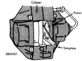 |
| PISTON ALIGNMENT |
Models With Rear Drum Brakes - Drum brakes must be adjusted before attempting to adjust handbrake. Handbrake should be adjusted if hand operated lever can be pulled up more than five notches. Adjust with handbrake lever completely disengage, by turning adjuster on cable and next to hand brake lever. Adjustment is correct when handbrake will lock rear wheels without passing through more than four or five notches on ratchet.
HYDRAULIC SYSTEM BLEEDING
NOTE - Manufacturer recommends replacing brake fluid entire system once a year to avoid moisture build-up. Attach a pressure bleeder to master cylinder reservoir. CAUTION - Do not exceed 29 psi. Raise and support vehicle and remove wheels. Attach a bleeder hose to bleeder screw, and immerse opposite end of hose into a container partially filled with brake fluid. Open bleeder screw, allow all air has been expelled from system. NOTE - On front wheel four piston calipers, bleed lower inboard screw before bleeding lower outboard screw.
REMOVAL AND INSTALLATION
DRUM BRAKE SHOES
Removal - Hoist vehicle, remove rear wheels and brake drums. Detach brake shoes from bottom support, then pull shoes out of wheel cylinders. Disconnect hand brake cable from rear shoes. Separate shoes by removing return springs.
Installation - Reverse removal procedure and note the following: Install long end of shoe push rod spring toward handbrake lever. Adjust brakes.
DISC PADS
Removal - Raise and support vehicle and remove wheels. Drive out retaining pins toward inside of vehicle and remove cross spring. Using a suitable extractor tool (3.9314-14002), remove disc pads from caliper assembly.
Installation - 1) NOTE - Replacement of disc pads should be done in complete sets only. Using a cylinder brush, clean guide surface and support surface in caliper. Siphon sufficient fluid from outer cylinder reservoir to prevent overflowing, then press pistons to bottom of bores.
2) On rear two piston calipers, ensure machines position of piston face makes a 20° angle to lower caliper wall. Install disc pads, cross spring and retaining pins. After installation, depress brake pedal several times to position pads against rotor.
CALIPER ASSEMBLY
Removal - Remove master cylinder reservoir cap and plug fluid outlet lines. Raise and support vehicle and remove tire and wheel assembly. Disconnect hydraulic line(s), remove caliper mounting bolts, and separate caliper from caliper from backing plate.
Installation - Reverse removal procedure and bleed hydraulic system.
ROTOR
Removal & Installation (Front) - With caliper assembly removed, remove hub grease cap, cotter pin, and nut. Remove hub and rotor assembly. Remove Allen head bolts retaining rotor to hub and remove rotor. To install, reverse removal procedure, tighten all bolts and fittings evenly, and bleed hydraulic system if necessary. Adjust front wheel bearing. See Wheel Bearing Adjustment in WHEEL ALIGNMENT Section.
Removal & Installation (Rear) - Remove rear wheel and caliper assembly, then pull rotor out from axle shaft flange. To install, reverse removal procedure, tighten all bolts and fittings evenly, and bleed hydraulic system if necessary.
PARKING BRAKE SHOES
Removal - With rear caliper and rotor removed, disconnect lower return spring using brake spring pliers. Turn retaining springs 90 degrees using suitable tool (7014) and remove. Pull brake shoes apart at bottom and lift away upwards.
Installation - Reverse removal procedure and adjust parking brake shoes and cables.
MASTER CYLINDER
Removal - Remove master cylinder reservoir cap and plug fluid outlet lines. Remove hose fittings from master cylinder and raise above reservoir fluid level. Mark hydraulic lines for reassembly reference and disconnect from master cylinder. Remove nuts attaching cylinder to power unit, and separate master cylinder from power brake unit.
Installation - Reverse removal procedure and note the following: Make sure rubber "O" ring seal between master cylinder and power unit is not damaged. Check clearance between power unit thrust rod and master cylinder piston with Plastigage and, if necessary, set to .020" by inserting a shim behind plunger head. Bleed hydraulic system and check for fluid leaks.
POWER BRAKE UNIT
Removal - 1) Remove air cleaner and battery, disconnect oil reservoir for power steering (if equipped) and move to one side. Block brake fluid reservoir outlets and remove hoses from master cylinder.
2) Remove lower left instrument panel housing and secure to one side. Remove brake pedal clevis pin, and disconnect vacuum hose from intake manifold. Remove hydraulic lines from master cylinder marking positions for reassembly reference. Remove nuts retaining power unit to support and remove power unit.
Installation - Reverse removal procedure, bleed hydraulic system, and check following adjustments: Adjust length of piston rod (A) to 14.49-14.53". Adjust pedal height (B) to 9.65". Adjust exposed depth of brake light switch plunger (C) to .24-.28". See illustration.
Check Valve Replacement - Check valve is located in power unit vacuum line at intake manifold. To remove, loosen hose clamps, remove vacuum hoses, and remove valve. To install, reverse removal procedure, making sure arrow or block portion of valve faces intake manifold.
Filter Replacement - With power brake unit removed from vehicle, pull back rubber dust boot and remove retaining ring. Remove silencer and filter. To install, reverse removal procedure.
REAR BRAKE PRESSURE LIMITER
Removal & Installation - Plug fluid outlets in brake fluid reservoir. Disconnect brake hose and rear brake lines from pressure limiter. Remove mounting bolts and pressure limiter. To install, reverse removal procedure and bleed hydraulic system.
ROTOR
Removal & Installation (Front) - With caliper assembly removed, remove hub grease cap, cotter pin, and nut. Remove hub and rotor assembly. Remove Allen head bolts retaining rotor to hub and remove rotor. To install, reverse removal procedure, tighten all bolts and fittings evenly, and bleed hydraulic system if necessary. Adjust front wheel bearing. See Wheel Bearing Adjustment in WHEEL ALIGNMENT Section.
Removal & Installation (Rear) - Remove rear wheel and caliper assembly, then pull rotor out from axle shaft flange. To install, reverse removal procedure, tighten all bolts and fittings evenly, and bleed hydraulic system if necessary.
PARKING BRAKE SHOES
Removal - With rear caliper and rotor removed, disconnect lower return spring using brake spring pliers. Turn retaining springs 90 degrees using suitable tool (7014) and remove. Pull brake shoes apart at bottom and lift away upwards.
Installation - Reverse removal procedure and adjust parking brake shoes and cables.
MASTER CYLINDER
Removal - Remove master cylinder reservoir cap and plug fluid outlet lines. Remove hose fittings from master cylinder and raise above reservoir fluid level. Mark hydraulic lines for reassembly reference and disconnect from master cylinder. Remove nuts attaching cylinder to power unit, and separate master cylinder from power brake unit.
 |
| POWER UNIT PUSH ROD ADJUSTMENTS |
Installation - Reverse removal procedure and note the following: Make sure rubber "O" ring seal between master cylinder and power unit is not damaged. Check clearance between power unit thrust rod and master cylinder piston with Plastigage and, if necessary, set to .020" by inserting a shim behind plunger head. Bleed hydraulic system and check for fluid leaks.
POWER BRAKE UNIT
Removal - 1) Remove air cleaner and battery, disconnect oil reservoir for power steering (if equipped) and move to one side. Block brake fluid reservoir outlets and remove hoses from master cylinder.
2) Remove lower left instrument panel housing and secure to one side. Remove brake pedal clevis pin, and disconnect vacuum hose from intake manifold. Remove hydraulic lines from master cylinder marking positions for reassembly reference. Remove nuts retaining power unit to support and remove power unit.
Installation - Reverse removal procedure, bleed hydraulic system, and check following adjustments: Adjust length of piston rod (A) to 14.49-14.53". Adjust pedal height (B) to 9.65". Adjust exposed depth of brake light switch plunger (C) to .24-.28". See illustration.
Check Valve Replacement - Check valve is located in power unit vacuum line at intake manifold. To remove, loosen hose clamps, remove vacuum hoses, and remove valve. To install, reverse removal procedure, making sure arrow or block portion of valve faces intake manifold.
Filter Replacement - With power brake unit removed from vehicle, pull back rubber dust boot and remove retaining ring. Remove silencer and filter. To install, reverse removal procedure.
REAR BRAKE PRESSURE LIMITER
Removal & Installation - Plug fluid outlets in brake fluid reservoir. Disconnect brake hose and rear brake lines from pressure limiter. Remove mounting bolts and pressure limiter. To install, reverse removal procedure and bleed hydraulic system.
OVERHAUL
DRUM BRAKE WHEEL CYLINDERDisassembly - With wheel brake drum removed, back off shoe adjusting cams, disconnect brake line and remove cylinder from backing plate. Disassemble wheel cylinder and pay particular attention to location and direction of parts.
Cleaning & Inspection - Clean all parts in alcohol or other suitable non oil base solvent. Discard all rubber parts and inspect all other parts for wear or damage.
Reassembly - Dip new parts in clean brake fluid or apply ATE cylinder paste. To install cylinder, reverse disassembly procedure and bleed brakes.
BRAKE CALIPER
Disassembly - With caliper removed from vehicle and disc pads remove from caliper, remove clamping rings and rubber protecting caps. Hold one piston in place using a suitable clamp, insert a piece of wood in caliper cavity, then apply compressed air to fluid inlet and remove opposite piston. Remove sealing ring using a suitable plastic tool. Remove remaining piston(s) and seal(s) in same manner. NOTE - DO NOT separate caliper halves unless a leak is detected. To disassemble, remove expansion bolts, separate caliper halves and remove sealing rings.
Cleaning & Inspection - Clean all parts in alcohol and check for wear or damage; replace parts as necessary.
 Reassembly - Reassemble caliper (if separated) using new seals and expansion bolts. Tighten expansion bolts from inside out. Coat pistons and caliper bores with ATE brake cylinder paste (or equivalent), install sealing rings, then install pistons into bores. Make sure pistons are not tilted when inserting. On two pison calipers, make sure machined surface of piston face makes a 20 degree angle to lower caliper wall. Install rubber protecting caps and clamp rings.
MASTER CYLINDER
Disassembly - Push in on primary piston and remove secondary piston stop screw. Remove snap ring from end of cylinder and remove primary and secondary piston assemblies and return spring. Disassemble piston assemblies noting number of parts used.
Cleaning & Inspection - Clean all parts in alcohol and inspect for wear or damage. NOTE - Cylinders with surface defects in bores must be replaced; do not overhaul.
Reassembly - Reassemble piston assemblies using a thin coating of ATE brake cylinder paste (or equivalent). Install piston assemblies into cylinder bore using a suitable guide sleeve (BMW 6063) to prevent damaging seals. Install secondary piston stop screw, making sure that piston is pushed fully forward before screw is installed and tightened. Install retaining ring in end of master cylinder bore.