Axle housing is banjo type with removable differential carrier and semi-floating axle shafts. Ring and pinion are hypoid type in which centerline of pinion is set below centerline of ring gear. Differential case may be either two pinion or four pinion design. The axle shafts are retained in housing by ball bearings and bearing retainers at axle housing outer ends.
All Mazda models use one basic type of rear axle assembly. Any differences in Removal and Installation or Overhaul procedures will be noted where they occur. To determine axle ratio, divide number of ring gear teeth by number of pinion teeth.
 |
| MEASURING PINION HEIGHT |
1) Mount carrier in a suitable repair stand. Attach a dial indicator to carrier (with button of indicator contacting backface of ring gear) and check ring gear deflection. Maximum allowable deflection is .004" (.1 mm); replace ring and pinion if above specification. Punch identification marks on side bearing supports of carrier, differential bearing caps, and side bearing adjusters. Remove adjuster lock plates, loosen bearing cap attaching nuts or bolts, and slightly back off adjusters to relieve preload.
2) Remove bearing caps and adjusters, then withdraw differential assembly from carrier, making sure side bearing races remain with their respective bearings. If necessary for replacement, use a suitable puller and remove side bearings from gear case. Straighten lock tabs, remove ring gear attaching bolts, and separate ring gear from gear case.
3) On all models except RX-4, drive out differential pinion shaft lock pin with a punch and remove pinion shaft. Rotate pinion gears 90 degrees and remove gears, thrust washers, thrust block (if equipped), and differential side gears. On RX-4 models, remove bolts joining differential case halves and separate case. Remove side gears, thrust washers, pinion gears, and spider.
4) On all models, remove pinion nut and pinion flange. Remove drive pinion and rear bearing assembly, adjusting shims (if equipped), spacer and bearing collar if used). NOTE -
It may be necessary to top end of pinion with soft hammer to remove from carrier. Remove front oil seal and withdraw front pinion bearing. Using a press, remove rear bearing from drive pinion, then lift off pinion adjusting shim. If necessary for replacement, use a drift punch and remove pinion bearing races from carrier.
 |
| MAZDA REAR AXLE ASSEMBLY |
REASSEMBLY AND ADJUSTMENTDrive Pinion Depth - 1) NOTE -
The use of a suitable dial indicator assembly (49 0727 570) and pinion gauging set (49 0305 555, all exc. pick-up; or 49 0603 555A, B1600 and RE pick-up) is required for this procedure. Install dial indicator on gauge body, place gauge body on a surface plate, and preload indicator .040-.120" (1-3 mm). When preloaded, turn outer ring of indicator assembly to "zero" gauge.
2) Make sure differential bearing bores are free of dirt and burrs, then install drive pinion, dummy bearing, and original pinion depth shim into carrier. Place gauge block on pinion and position indicator assembly on block so button of indicator contacts lowest portion of differential bore.
3) Record the amount indicator moves in a "+" (plus) or "-" (minus) direction from zero. Remove gauging assembly and pinion from carrier. Check rear face of pinion for the machining correction figure. If pinion is marked "+" (plus), SUBTRACT amount specified on pinion from dial indicator reading; if marked "-" (minus), ADD amount to indicator reading. NOTE - Figures on pinion are hundredth millimeters.
4) Place dummy pinion and rear pinion bearing on surface plate and compare heights. If pinion bearings is higher than dummy bearing, SUBTRACT difference from dial indicator reading, if pinion bearing is lower than dummy bearing, ADD amount to indicator reading.
5) Select correct pinion depth adjusting shim to be used for reassembly by adding or subtracting the amount determined in steps 2), 3), and 4) from the thickness of the original pinion depth shim used during gauging process. Position correct shim on pinion and install pinion bearing. Shims are available in the following thicknesses for all models except RX-4:
Identification Mark Thickness In. (mm)08....................................................... .121 (3.08)
11....................................................... .122 (3.11)
14....................................................... .124 (3.14)
17....................................................... .125 (3.17)
20....................................................... .126 (3.20)
23....................................................... .127 (3.23)
26....................................................... .128 (3.26)
29....................................................... .130 (3.29)
32....................................................... .131 (3.32)
35....................................................... .132 (3.35)
38....................................................... .133 (3.38)
41....................................................... .134 (3.41)
44....................................................... .135 (3.44)
 |
SOLID BEARING PRELOAD SPACER
AND SHIMS |
47....................................................... .137 (3.47)
For RX-4 models, the following thickness shims are available
Identification Mark Thickness In. (mm)52....................................................... .139 (3.52)
55....................................................... .140 (3.55)
58....................................................... .141 (3.58)
61....................................................... .142 (3.61)
64....................................................... .143 (3.64)
67....................................................... .145 (3.67)
70....................................................... .146 (3.70)
73....................................................... .147 (3.73)
Pinion Bearing Preload (W/ Solid Bearing Spacer) - 1) Position drive pinion and rear bearing assembly into carrier, then install bearing spacer and preload shims onto pinion. Install front pinion bearing and pinion flange (do not install oil seal at this time). Install pinion nut and tighten to 110 ft. lbs. (15 mkg) on 1200 models or 130 ft. lbs. (18 mkg) on R-100 models.
2) Using a torque wrench installed on pinion nut, measure turning torque of drive pinion through at least one full revolution. If preload is greater than specified (see Axle Assembly Specifications), a thicker shim or longer bearing spacer is required; if preload is less than specified, a thinner shim or shorter bearing spacer is required. Shims and spacer are available in the following thicknesses and lengths:
Identification Mark Thickness/Length In. (mm) |
INSTALLING COLLAPSIBLE
BEARING SPACER |
Shims
4..................................................... .013 (.34)
6..................................................... .014 (.36)
8..................................................... .015 (.38)
Spacer (1200 Model Only)
10................................................... 1.658 (41.10)
18................................................... 1.661 (41.18)
26................................................... 1.664 (41.26)
34................................................... 1.668 (41.34)
Spacer (R-100 Model Only)
60................................................... 2.149 (54.60)
68................................................... 2.152 (54.68)
76................................................... 2.155 (54.76)
84................................................... 2.159 (54.84)
 |
INSTALLING PINION SHAFT
& LOCK PIN |
3) After obtaining correct preload shim pack, remove pinion flange, install pinion oil seal, and reinstall pinion oil seal, and reinstall pinion flange. Tighten pinion nut to specification.
Pinion Bearing Preload (W/Collapsible Bearing Spacer) - 1) Position drive pinion in carrier and install bearing spacer. Place front pinion bearing in position on pinion gear, hold gear fully forward, and drive bearing over pinion until seated. Apply grease to lip of pinion by tapping with a soft hammer. Install pinion washer and nut. Before tightening nut (when pinion preload is zero), check oil seal drag using a torque wrench. Tighten pinion nut as follows:
Application Ft. Lbs. (mkg)808 (W/1300 cc)................................... 87 (12)
 |
INSTALLING DIFFERENTIAL
ASSEMBLY |
RX-4.................................................... 101(14)
B1600, RE (Rotary Pick-Up)................... 145(20)
All Others.............................................. 94(13)
2) With nut tightened, check preload using a torque wrench mounted on pinion nut. If preload is not as specified (see Axle Assembly Specifications), continue tightening nut and checking preload until specified preload is obtained. CAUTION - Preload builds quickly. Nut should be tightened a little at a time and preload checked after each slight amount of tightening.
Case Assembly - 1) On all models except RX-4, install a thrust washer on each differential side gear and install into case. Through openings in gear case, insert pinion gears exactly 180 degrees opposite each other. Rotate pinion gears 90 degrees so holes in gears line up with pinion shaft holes in gear case. Insert pinion shaft through case and pinion gears.
 |
ADJUSTING BEARING PRELOAD
(CASE SPREAD) |
2) On RX-4 models, install a thrust washer on each differential side gear and install into case halves. Position pinion gears on spider and install spider into differential case half. Align identification marks, mate case halves, and install and tighten retaining bolts.
3) On all models, check backlash between side gears and pinion gears. Backlash should be less than .004" (.1 mm); if not, install selective thrust washers to bring backlash within specifications. Washers are available in thicknesses of .063" (1.6 mm), .067" (1.7 mm), .071" (1.8 mm), .079" (2.0 mm), .083" (2.1 mm), and .087" (2.2 mm). NOTE -
Always use some thickness thrust washer for both side gears. 4)
4) If equipped with thrust block, remove pinion shaft, install thrust block, and reinstall pinion shaft. On all models except RX-4, drive lock pin into case to secure pinion shaft. Using a punch, shake lock pin into case to secure pinion shaft. Using a punch, stake lock pin hole to prevent pin from working loose. On all models, mount ring gear on case, then install and tighten ring gear attaching bolts. If removed, instal differential side bearings.
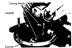
Backlash & Side Bearing Preload - 1) Place differential case assembly into carrier making sure timing marks on ring and pinion gears are aligned. Install bearing adjusters and bearing caps, then tighten bearing cap nuts or bolts finger tight. Turn adjusters with a suitable spanner wrench (49 0259 720) until bearing end play is eliminated and some backlash exists between ring gear and pinion. Slightly tighten one bearing cap nut or bolt on each side carrier.
2) Mount a dial indicator to carrier flange so button of indicator contacts of the ring gear teeth at a right angle then check backlash between ring and pinion gears. Using the spanner wrench, turn both bearing adjusters equally until backlash is as specified in Axle Assembly Specifications.
3) Differential bearing preload (case spread) is obtained by tightening both bearing adjusters equally. Tighten adjusters until the distance between pilot section of side bearing caps in as specified in Axle Assembly Specifications. Tighten bearing cap nuts or bolts, then recheck backlash adjustement. Make a gear tooth pattern check to insure correct assembly, then install adjuster lock plates on bearing caps.


