Showing posts with label wheel. Show all posts

LUV 1974 76 Wheel Alignment Repair Guide

| 0 comments |
LUV SPECIFICATIONS AND ADJUSTMENTS
TIRE INFLATION
Before checking or adjusting wheel alignment, ensure tires are correctly inflated. Refer to manufacturers specifications located in glove box or an right hand door jam.

RIDING HEIGHT
1) Place vehicle on smooth level surface. Bounce vehicle several times. Raise vehicle and allow to settle at normal height6. Measure distance as shown in illustration.


NOTE - Height check should be made with a full tank of gas, spare tire installed, and jack included. No passengers should be in vehicle.

2) Difference between measurements of each side must not be more than 1/2". If an adjustment is necessary, it can be made at bolt on height control arm

Riding Height Specifications
Front - 4.6"
Rear - 7.4"

CASTER
Adjustment is made with shims inserted between upper control arm pivot shaft and frame. Adding or subtracting shims from either front or rear bolts will effect a change in caster. Shims may not be transfered from front to rear or from rear to front. Transfer of one shim from front bolt to rear bolt will decrease positive caster. For correct specifications, refer to table

CAMBER
Camber is adjusted by adding or subtracting shims. Adding on equal number of shims at both front and rear of pivot shaft will decrease positive camber. For correct specifications, refer to table.

TOE-IN
NOTE - Toe-in must be adjusted after caster and camber adjustment.

Toe-in can be adjusted by rotating the intermediate rod after loosening lock nuts. Rotating intermediate rod towards front of vehicle reduces toe-in and towards rear of vehicle increases toe-in. For correct specifications, refer to following guide table.


Read More..

Mazda 1974 76 Models Wheel Alignment Repair Guide

| 0 comments |
MAZDA SPECIFICATIONS AND ADJUSTMENTS

TIRE INFLATION (COLD)
Before attempting to check or adjust wheel alignment, make sure tires are properly inflated. Refer to manufacturers specifications given in owners manual.

CASTER
808, RX2 & RX3 MODELS - Caster is not adjustable. If caster angle is not to specifications, inspect suspension for wear or damage and repair or replace components as necessary.

RX4 - Caster and camber angles can be adjusted by changing position of the shock absorber support. To adjust remove four nuts attaching shock absorber support to fender apron. Raise front of vehicle and support with jack stands, then remove wheel on side to be adjusted. Press shock absorber downward and change position of support according to following table and illustration. Tighten shock absorber support attaching nuts. Install wheel, lower vehicle and recheck caster and camber angles.


Pickup - To adjust, change shims between upper arm shaft and support bracket or turn upper arm shaft until specifications are obtained.


CAMBER

808, RX2, and RX3 - Camber is not adjustable. If camber angle is not to specifications, inspect suspension for wear or damage and repair or replace components as necessary.

RX4 - See procedure given under Caster adjustment.

Pickup - To adjust, change shims between upper arm shaft and support bracket until specifications for camber are within limits.

TOE-IN
All Models - Position wheels to center position and loosen tie rod locking nuts at each end of tie rod. Check that tie rod ends are in the same position on each rod ensuring that the tie rods are the same length. Turn tie rods by equal amounts until the toe-in is within specifications. Tighten locking nuts.


Read More..

1970 73 Capri All Models Wheel Alignment

| 0 comments |
1970-73 CAPRI SPECIFICATIONS AND ADJUSTMENTS

TIRE INFLATION (COLD)
Before attempting to check or adjust wheel alignment, ensure that tires are properly inflated. Refer to manufacturers specifications located on right hand sun visor.

CASTER
All Models - Caster is nonadjustable. If not within specifications, check front suspension for damage. Repair or replace parts as necessary.

CAMBER
All Models - Camber is non adjustable. If not within specifications, check front suspension for damage. Repair or replace parts as necessary

TOE-IN
All Models - Position wheels in straight ahead position and loosen tie rod end lock nut and clips securing bellows. To adjust toe-in, rotate tie rods until specifications are within limits. Tighten lock nuts and secure clips. Tie rods should be equal within 1/4".


Read More..

1974 Capri Wheel Alignment

| 0 comments |
CAPRI SPECIFICATIONS AND ADJUSTMENT

TIRE INFLATION (COLD)
Before attempting to check or adjust wheel alignment, make sure that tires are properly inflated. Refer to manufacturers specifications, located inside glove box door.

CASTER
All Models - Caster is nonadjustable. If not within specifications, check front suspension for damage. Repair or replace parts as necessary.

CAMBER
All Models - Camber is non adjustable. If not within specification, check front suspension for damage. Repair or replace parts as necessary.

TOE-IN
All Models - Position wheels in straight-ahead position and loosen tie rod end lock nut and clips securing bellows. To adjust toe-in, rotate tie rods until specifications are within limits. Tighten lock nuts and secure clips. Tie rods lengths should be equal within 1/4".

1974 Capri Models

1975 Capri Models

Read More..

Pantera 1973 74 Wheel Alignment Repair Guide

| 0 comments |
1973-74  PANTERA SPECIFICATIONS AND ADJUSTMENTS

TIRE INFLATION (COLD)
Before attempting to check or adjust wheel alignment, make sure tires are properly inflated. Refer to manufacturers specifications given in owners manual.

RIDING HEIGHT
NOTE - Vehicle must be loaded to simulate normal road condition, before attempting to check or adjust wheel alignment.

CASTER
Caster angle is not adjustable. If caster angle is not within specifications, inspect suspension system for wear or damage and repair or replace components as necessary.

CAMBER
Front - With normal loaded condition simulated, measure camber angle. If adjustment is necessary, loosen bolts on upper control arm ball joint. Move ball joint in or out to obtained specified angle. Tighten bolts.

Rear - If rear camber angle is not to specifications, adjust by adding or removing an equal number of shims between lower control arm attaching bracket and the frame. NOTE - An equal number of shims must be added or removed at both attaching brackets.

TOE-IN
Front - Set wheels in straight-ahead position and measure toe-in. If adhustment is necessary, loosen lock nuts on steering link (tie rods) adjusting sleeves. Rotate each sleeve on equal amount until correct toe-in is obtained. NOTE - After adjustment, both steering links (tie rods) should be of equal length.

Rear - Back vehicle onto alignment machine, and note that a toe-out condition will be indicated. If adjustment is necessary, loosen lower control arm attaching bracket both and insert horseshoe shims behind lower control arm attaching bracket. NOTE - After adjusting toe-in, thickness of shims should be about equal on each side of vehicle.
1973
1974


Read More..

Saab 1974 Wheel Alignment Repair Guide

| 0 comments |
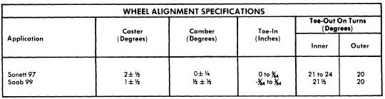
1974 SAAB SPECIFICATIONS AND ADJUSTMENTS

TIRE INFLATION (COLD)
Before attempting to check or adjust wheel alignment, make sure tires are properly inflated. Refer to manufacturers specifications given in owners manual.

CASTER
All Models - To adjust caster, add or remove shims under upper control arm bushing brackets. Changing shims from front to rear bracket increases caster angle. Moving shims from rear to front decreases caster angle. Note - Some thickness of shims removed from front must be placed under rear and vice versa. Change in caster also affects camber.

CAMBER
All Models - To adjust camber, add or remove shims under upper control arm bushing brackets. Increasing shims under both brackets reduces camber angle and removing shims under both increases camber. NOTE - Always add or remove some thickness of shims at front and rear or caster angle will be affected.

TOE-IN
All Models - With wheels in straight-ahead position, loosen steering link (tie rod) lock nut and turn adjustable sleeve until correct toe-in is obtained. Tighten lock nuts and recheck toe-in.

NOTE -  After adjustment of toe-in, measurement A (see illustration) of tie rod must not exceed 1.6" (with key grip) or 1.2" (without key grip). For tie rods opposite to each other the difference between the measurement A must not exceed .08".


Read More..