Carburetor Adjustments How to Adjust Your Carburetor After Carburetor Rebuild
| 0 comments |Labels: adjust, adjustments, after, carburetor, how, rebuild, to, your
BMW 635CSi 1985 Electrical Repair
| 0 comments |Labels: 1985, 635csi, BMW, electrical, Repair
Electrical Troubleshooting Manual, Schematics and Wiring Diagrams For:
Manufacturer: BMW
Model: 635CSi E24
Year: 1985
Quick Reference Index:

Read More..
Manufacturer: BMW
Model: 635CSi E24
Year: 1985
Quick Reference Index:

- Power Distribution Box
- Fuse Data
- Diagnostic Connector
- Start
- Fuel Delivery/ Evaporative Control
- Fuel Control/ Idle Speed Control
- Ignition and Charging System
- Wiper/ Washer
- Speedometer/ Gauges/ Warning Indicators
- Active Check Control
- Brake Lining Warning
- Ignition Key Warning Seatbelt Warning
- Headlights/ Fog Lights/ Turn/ Hazard Warning
- Front Park/ Front Maker/ Tail
- Rear Marker/ License/ Trunk
- Cruise Control/ Stop Lights
- Dash Lights/ Interior Lights/ Dash/ Transmission Range
- Back Up/ Transmission Range
- Cigar Lighter/ Glove Box Light/ Digital Clock/ Auto-Charging Flashlight
- Horn/ Sunroof/ Rear Defogger/ Power Windows/ Mirrors/ Central Locking (select)
- Central Locking (control)/ Radio/ Power Antenna/ Auxiliary Fan/ Heater/ Air Conditioning
- Ground Distribution/ Component Locations/ Notes/ Windshield Wipers Jet Heaters
- Splice Locations (Front, Middle, Engine, Rear Harnesses)
File Size: 9 MB
File Type: PDF, ZIP
Mazda 1968 74 Models Drive Axles Repair Manual
| 0 comments |Labels: 1968, 74, axles, Drive, Manual, Mazda, models, Repair
MODELS COVERED:
Installation (All Exc. Pick-Up - 1) Apply a light coat of grease to oil seal in axle housing. Check axle shaft end clearance as follows. Install backing plate and gasket temporarily and measure depth of bearing seat in axle housing. Then measure width of axle bearing outer race. The difference between the two measurements indicates the required thickness of shim.
Removal (B1600 and Pick-Up) - Remove wheel and tire assembly, then remove brake drum and brake shoes. Remove parking brake cable retainer and disconnect brake lines at wheel cylinders. Remove nuts attaching backing plate and bearing housing to axle housing, then pull axle shaft, backing plate, bearing housing assembly, and shims off axle housng.
1) Mount carrier in a suitable repair stand. Attach a dial indicator to carrier (with button of indicator contacting backface of ring gear) and check ring gear deflection. Maximum allowable deflection is .004" (.1 mm); replace ring and pinion if above specification. Punch identification marks on side bearing supports of carrier, differential bearing caps, and side bearing adjusters. Remove adjuster lock plates, loosen bearing cap attaching nuts or bolts, and slightly back off adjusters to relieve preload.
2) Remove bearing caps and adjusters, then withdraw differential assembly from carrier, making sure side bearing races remain with their respective bearings. If necessary for replacement, use a suitable puller and remove side bearings from gear case. Straighten lock tabs, remove ring gear attaching bolts, and separate ring gear from gear case.
3) On all models except RX-4, drive out differential pinion shaft lock pin with a punch and remove pinion shaft. Rotate pinion gears 90 degrees and remove gears, thrust washers, thrust block (if equipped), and differential side gears. On RX-4 models, remove bolts joining differential case halves and separate case. Remove side gears, thrust washers, pinion gears, and spider.
4) On all models, remove pinion nut and pinion flange. Remove drive pinion and rear bearing assembly, adjusting shims (if equipped), spacer and bearing collar if used). NOTE - It may be necessary to top end of pinion with soft hammer to remove from carrier. Remove front oil seal and withdraw front pinion bearing. Using a press, remove rear bearing from drive pinion, then lift off pinion adjusting shim. If necessary for replacement, use a drift punch and remove pinion bearing races from carrier.
REASSEMBLY AND ADJUSTMENT
Drive Pinion Depth - 1) NOTE -The use of a suitable dial indicator assembly (49 0727 570) and pinion gauging set (49 0305 555, all exc. pick-up; or 49 0603 555A, B1600 and RE pick-up) is required for this procedure. Install dial indicator on gauge body, place gauge body on a surface plate, and preload indicator .040-.120" (1-3 mm). When preloaded, turn outer ring of indicator assembly to "zero" gauge.
2) Make sure differential bearing bores are free of dirt and burrs, then install drive pinion, dummy bearing, and original pinion depth shim into carrier. Place gauge block on pinion and position indicator assembly on block so button of indicator contacts lowest portion of differential bore.
3) Record the amount indicator moves in a "+" (plus) or "-" (minus) direction from zero. Remove gauging assembly and pinion from carrier. Check rear face of pinion for the machining correction figure. If pinion is marked "+" (plus), SUBTRACT amount specified on pinion from dial indicator reading; if marked "-" (minus), ADD amount to indicator reading. NOTE - Figures on pinion are hundredth millimeters.
4) Place dummy pinion and rear pinion bearing on surface plate and compare heights. If pinion bearings is higher than dummy bearing, SUBTRACT difference from dial indicator reading, if pinion bearing is lower than dummy bearing, ADD amount to indicator reading.
5) Select correct pinion depth adjusting shim to be used for reassembly by adding or subtracting the amount determined in steps 2), 3), and 4) from the thickness of the original pinion depth shim used during gauging process. Position correct shim on pinion and install pinion bearing. Shims are available in the following thicknesses for all models except RX-4:
Identification Mark Thickness In. (mm)
08....................................................... .121 (3.08)
11....................................................... .122 (3.11)
14....................................................... .124 (3.14)
17....................................................... .125 (3.17)
20....................................................... .126 (3.20)
23....................................................... .127 (3.23)
26....................................................... .128 (3.26)
29....................................................... .130 (3.29)
32....................................................... .131 (3.32)
35....................................................... .132 (3.35)
38....................................................... .133 (3.38)
41....................................................... .134 (3.41)
44....................................................... .135 (3.44)
47....................................................... .137 (3.47)
For RX-4 models, the following thickness shims are available
Identification Mark Thickness In. (mm)
52....................................................... .139 (3.52)
55....................................................... .140 (3.55)
58....................................................... .141 (3.58)
61....................................................... .142 (3.61)
64....................................................... .143 (3.64)
67....................................................... .145 (3.67)
70....................................................... .146 (3.70)
73....................................................... .147 (3.73)
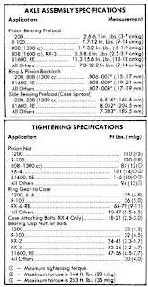
Pinion Bearing Preload (W/ Solid Bearing Spacer) - 1) Position drive pinion and rear bearing assembly into carrier, then install bearing spacer and preload shims onto pinion. Install front pinion bearing and pinion flange (do not install oil seal at this time). Install pinion nut and tighten to 110 ft. lbs. (15 mkg) on 1200 models or 130 ft. lbs. (18 mkg) on R-100 models.
2) Using a torque wrench installed on pinion nut, measure turning torque of drive pinion through at least one full revolution. If preload is greater than specified (see Axle Assembly Specifications), a thicker shim or longer bearing spacer is required; if preload is less than specified, a thinner shim or shorter bearing spacer is required. Shims and spacer are available in the following thicknesses and lengths:
Identification Mark Thickness/Length In. (mm)
Shims
4..................................................... .013 (.34)
6..................................................... .014 (.36)
8..................................................... .015 (.38)
Spacer (1200 Model Only)
10................................................... 1.658 (41.10)
18................................................... 1.661 (41.18)
26................................................... 1.664 (41.26)
34................................................... 1.668 (41.34)
Spacer (R-100 Model Only)
60................................................... 2.149 (54.60)
68................................................... 2.152 (54.68)
76................................................... 2.155 (54.76)
84................................................... 2.159 (54.84)
3) After obtaining correct preload shim pack, remove pinion flange, install pinion oil seal, and reinstall pinion oil seal, and reinstall pinion flange. Tighten pinion nut to specification.
Pinion Bearing Preload (W/Collapsible Bearing Spacer) - 1) Position drive pinion in carrier and install bearing spacer. Place front pinion bearing in position on pinion gear, hold gear fully forward, and drive bearing over pinion until seated. Apply grease to lip of pinion by tapping with a soft hammer. Install pinion washer and nut. Before tightening nut (when pinion preload is zero), check oil seal drag using a torque wrench. Tighten pinion nut as follows:
Application Ft. Lbs. (mkg)
808 (W/1300 cc)................................... 87 (12)
RX-4.................................................... 101(14)
B1600, RE (Rotary Pick-Up)................... 145(20)
All Others.............................................. 94(13)
2) With nut tightened, check preload using a torque wrench mounted on pinion nut. If preload is not as specified (see Axle Assembly Specifications), continue tightening nut and checking preload until specified preload is obtained. CAUTION - Preload builds quickly. Nut should be tightened a little at a time and preload checked after each slight amount of tightening.
Case Assembly - 1) On all models except RX-4, install a thrust washer on each differential side gear and install into case. Through openings in gear case, insert pinion gears exactly 180 degrees opposite each other. Rotate pinion gears 90 degrees so holes in gears line up with pinion shaft holes in gear case. Insert pinion shaft through case and pinion gears.
2) On RX-4 models, install a thrust washer on each differential side gear and install into case halves. Position pinion gears on spider and install spider into differential case half. Align identification marks, mate case halves, and install and tighten retaining bolts.
3) On all models, check backlash between side gears and pinion gears. Backlash should be less than .004" (.1 mm); if not, install selective thrust washers to bring backlash within specifications. Washers are available in thicknesses of .063" (1.6 mm), .067" (1.7 mm), .071" (1.8 mm), .079" (2.0 mm), .083" (2.1 mm), and .087" (2.2 mm). NOTE - Always use some thickness thrust washer for both side gears.
 4) If equipped with thrust block, remove pinion shaft, install thrust block, and reinstall pinion shaft. On all models except RX-4, drive lock pin into case to secure pinion shaft. Using a punch, shake lock pin into case to secure pinion shaft. Using a punch, stake lock pin hole to prevent pin from working loose. On all models, mount ring gear on case, then install and tighten ring gear attaching bolts. If removed, instal differential side bearings.
Backlash & Side Bearing Preload - 1) Place differential case assembly into carrier making sure timing marks on ring and pinion gears are aligned. Install bearing adjusters and bearing caps, then tighten bearing cap nuts or bolts finger tight. Turn adjusters with a suitable spanner wrench (49 0259 720) until bearing end play is eliminated and some backlash exists between ring gear and pinion. Slightly tighten one bearing cap nut or bolt on each side carrier.
2) Mount a dial indicator to carrier flange so button of indicator contacts of the ring gear teeth at a right angle then check backlash between ring and pinion gears. Using the spanner wrench, turn both bearing adjusters equally until backlash is as specified in Axle Assembly Specifications.
3) Differential bearing preload (case spread) is obtained by tightening both bearing adjusters equally. Tighten adjusters until the distance between pilot section of side bearing caps in as specified in Axle Assembly Specifications. Tighten bearing cap nuts or bolts, then recheck backlash adjustement. Make a gear tooth pattern check to insure correct assembly, then install adjuster lock plates on bearing caps.
- 616 (1971)
- 618 (1972-73)
- 808 (1972-74)
- 1200 (1971-72)
- B1600 (1972-74)
- R100 (1971-72)
- RX-2 (1971-74)
- RX-3 (1972-74)
- RX-4 (1974)
- RE (Rotary Pick-Up) (1974)
DESCRIPTION
Axle housing is banjo type with removable differential carrier and semi-floating axle shafts. Ring and pinion are hypoid type in which centerline of pinion is set below centerline of ring gear. Differential case may be either two pinion or four pinion design. The axle shafts are retained in housing by ball bearings and bearing retainers at axle housing outer ends.
AXLE RATIO AND IDENTIFICATION
All Mazda models use one basic type of rear axle assembly. Any differences in Removal and Installation or Overhaul procedures will be noted where they occur. To determine axle ratio, divide number of ring gear teeth by number of pinion teeth.
REMOVAL AND INSTALLATION
Axle Shaft and Bearings
Removal (All. Exc. Pick-Up) - Remove wheel and tire assembly and brake drum. Remove brake shoe return springs and brake shoes. On RX-4 models, remove center cap adapter from axle shaft flange. On all models, withdraw nuts attaching retainer and backing plate to axle housing, then use a suitable puller (49 0259 631 and 49 0223 630A) to remove axle from housing.
Bearing Replacement (All Exc. Pick-Up) - Remove axle bearing and collar using a press and a suitable bearing adapter (49 0259 745). NOTE - If pressure necessary to remove bearing exceeds 10 tons, or if bearing adapter is not available, grind bearing retaining collar down and cut with a chisel to remove. To reassemble, apply a light coat of oil to axle shaft and place bearing retainer and spacer on shaft. Position bearing on shaft with sealed side toward axle shaft flange, then press bearing on shaft until spacer contacts shaft shoulder. Next, press bearing retaining collar on shaft until it seats firmly against bearing. NOTE - Do not press bearing and collar on shaft at the same time. In addition, if collar is installed with less than 3 tons of pressure, replace a new part.
 |
| AXLE SHAFT ASSEMBLY (EXCEPT PICK-UP) |
2) Shims are available in thicknesses of .004" (.1 mm) and .016" (.4 mm). After selecting correct shim pack, apply sealant to shims and position brake backing plate and shims on axle housing. Install axle shaft assembly in housing using a new gasket, then install and tighten retainer bolts. At this time, recheck end play, maximum end play allowable is .004" (.1 mm). Install brake shoes, return springs, brake drum and wheel and tire assembly.
 |
| AXLE SHAFT ASSEMBLY (B1600 & RE PICK-UP) |
Bearing Replacement (B1600 and RE Pick-Up) - Straighten tools of lock washer, and using a suitable spanner wrench (49 0603 621A), remove lock nut and lock washer. Using a puller withdraw bearing and housing assembly from axle shaft, then remove backing plate. Remove bearing and oil seal from housing. To reassemble, reverse disassembly procedure.
Installation (B1600 and RE Pick-Up) 1) Install axle shaft, backing plate, and bearing housing to rear axle housing, temporarily attaching with two bolts and nuts. Mount a dial indicator on backing plate and check axle shaft end play. End play should be .002-.006" (.05-.15 mm).
2) NOTE - If both axle shafts were removed, a special procedure must be followed: The end play for the first axle shaft installed should be set to .026-.033" (.65-.85 mm). The second axle shaft installed should be set to the normal end play of .002-.006" (.05-.15 mm).
DIFFERENTIAL CARRIER
Removal and Installation - Raise vehicle until rear wheels are clear of ground. Remove drain plug and drain rear axle lubricant, reinstall plug and tighten. Remove axle shafts. Mark propeller shaft and pinion flange for reassembly reference, then disconnect propeller shaft. Remove carrier attaching nuts and withdraw carrier from axle housing. To install, reverse removal procedure, making sure to refill axle with lubricant.
OVERHAUL
Disassembly
 |
| MEASURING PINION HEIGHT |
2) Remove bearing caps and adjusters, then withdraw differential assembly from carrier, making sure side bearing races remain with their respective bearings. If necessary for replacement, use a suitable puller and remove side bearings from gear case. Straighten lock tabs, remove ring gear attaching bolts, and separate ring gear from gear case.
3) On all models except RX-4, drive out differential pinion shaft lock pin with a punch and remove pinion shaft. Rotate pinion gears 90 degrees and remove gears, thrust washers, thrust block (if equipped), and differential side gears. On RX-4 models, remove bolts joining differential case halves and separate case. Remove side gears, thrust washers, pinion gears, and spider.
4) On all models, remove pinion nut and pinion flange. Remove drive pinion and rear bearing assembly, adjusting shims (if equipped), spacer and bearing collar if used). NOTE - It may be necessary to top end of pinion with soft hammer to remove from carrier. Remove front oil seal and withdraw front pinion bearing. Using a press, remove rear bearing from drive pinion, then lift off pinion adjusting shim. If necessary for replacement, use a drift punch and remove pinion bearing races from carrier.
 |
| MAZDA REAR AXLE ASSEMBLY |
REASSEMBLY AND ADJUSTMENT
Drive Pinion Depth - 1) NOTE -The use of a suitable dial indicator assembly (49 0727 570) and pinion gauging set (49 0305 555, all exc. pick-up; or 49 0603 555A, B1600 and RE pick-up) is required for this procedure. Install dial indicator on gauge body, place gauge body on a surface plate, and preload indicator .040-.120" (1-3 mm). When preloaded, turn outer ring of indicator assembly to "zero" gauge.
2) Make sure differential bearing bores are free of dirt and burrs, then install drive pinion, dummy bearing, and original pinion depth shim into carrier. Place gauge block on pinion and position indicator assembly on block so button of indicator contacts lowest portion of differential bore.
3) Record the amount indicator moves in a "+" (plus) or "-" (minus) direction from zero. Remove gauging assembly and pinion from carrier. Check rear face of pinion for the machining correction figure. If pinion is marked "+" (plus), SUBTRACT amount specified on pinion from dial indicator reading; if marked "-" (minus), ADD amount to indicator reading. NOTE - Figures on pinion are hundredth millimeters.
4) Place dummy pinion and rear pinion bearing on surface plate and compare heights. If pinion bearings is higher than dummy bearing, SUBTRACT difference from dial indicator reading, if pinion bearing is lower than dummy bearing, ADD amount to indicator reading.
5) Select correct pinion depth adjusting shim to be used for reassembly by adding or subtracting the amount determined in steps 2), 3), and 4) from the thickness of the original pinion depth shim used during gauging process. Position correct shim on pinion and install pinion bearing. Shims are available in the following thicknesses for all models except RX-4:
Identification Mark Thickness In. (mm)
08....................................................... .121 (3.08)
11....................................................... .122 (3.11)
14....................................................... .124 (3.14)
17....................................................... .125 (3.17)
20....................................................... .126 (3.20)
23....................................................... .127 (3.23)
26....................................................... .128 (3.26)
29....................................................... .130 (3.29)
32....................................................... .131 (3.32)
35....................................................... .132 (3.35)
38....................................................... .133 (3.38)
41....................................................... .134 (3.41)
44....................................................... .135 (3.44)
| SOLID BEARING PRELOAD SPACER AND SHIMS |
For RX-4 models, the following thickness shims are available
Identification Mark Thickness In. (mm)
52....................................................... .139 (3.52)
55....................................................... .140 (3.55)
58....................................................... .141 (3.58)
61....................................................... .142 (3.61)
64....................................................... .143 (3.64)
67....................................................... .145 (3.67)
70....................................................... .146 (3.70)
73....................................................... .147 (3.73)
Pinion Bearing Preload (W/ Solid Bearing Spacer) - 1) Position drive pinion and rear bearing assembly into carrier, then install bearing spacer and preload shims onto pinion. Install front pinion bearing and pinion flange (do not install oil seal at this time). Install pinion nut and tighten to 110 ft. lbs. (15 mkg) on 1200 models or 130 ft. lbs. (18 mkg) on R-100 models.
2) Using a torque wrench installed on pinion nut, measure turning torque of drive pinion through at least one full revolution. If preload is greater than specified (see Axle Assembly Specifications), a thicker shim or longer bearing spacer is required; if preload is less than specified, a thinner shim or shorter bearing spacer is required. Shims and spacer are available in the following thicknesses and lengths:
Identification Mark Thickness/Length In. (mm)
| INSTALLING COLLAPSIBLE BEARING SPACER |
4..................................................... .013 (.34)
6..................................................... .014 (.36)
8..................................................... .015 (.38)
Spacer (1200 Model Only)
10................................................... 1.658 (41.10)
18................................................... 1.661 (41.18)
26................................................... 1.664 (41.26)
34................................................... 1.668 (41.34)
Spacer (R-100 Model Only)
60................................................... 2.149 (54.60)
68................................................... 2.152 (54.68)
76................................................... 2.155 (54.76)
84................................................... 2.159 (54.84)
 |
| INSTALLING PINION SHAFT & LOCK PIN |
Pinion Bearing Preload (W/Collapsible Bearing Spacer) - 1) Position drive pinion in carrier and install bearing spacer. Place front pinion bearing in position on pinion gear, hold gear fully forward, and drive bearing over pinion until seated. Apply grease to lip of pinion by tapping with a soft hammer. Install pinion washer and nut. Before tightening nut (when pinion preload is zero), check oil seal drag using a torque wrench. Tighten pinion nut as follows:
Application Ft. Lbs. (mkg)
808 (W/1300 cc)................................... 87 (12)
 |
| INSTALLING DIFFERENTIAL ASSEMBLY |
B1600, RE (Rotary Pick-Up)................... 145(20)
All Others.............................................. 94(13)
2) With nut tightened, check preload using a torque wrench mounted on pinion nut. If preload is not as specified (see Axle Assembly Specifications), continue tightening nut and checking preload until specified preload is obtained. CAUTION - Preload builds quickly. Nut should be tightened a little at a time and preload checked after each slight amount of tightening.
Case Assembly - 1) On all models except RX-4, install a thrust washer on each differential side gear and install into case. Through openings in gear case, insert pinion gears exactly 180 degrees opposite each other. Rotate pinion gears 90 degrees so holes in gears line up with pinion shaft holes in gear case. Insert pinion shaft through case and pinion gears.
 |
| ADJUSTING BEARING PRELOAD (CASE SPREAD) |
3) On all models, check backlash between side gears and pinion gears. Backlash should be less than .004" (.1 mm); if not, install selective thrust washers to bring backlash within specifications. Washers are available in thicknesses of .063" (1.6 mm), .067" (1.7 mm), .071" (1.8 mm), .079" (2.0 mm), .083" (2.1 mm), and .087" (2.2 mm). NOTE - Always use some thickness thrust washer for both side gears.
 4) If equipped with thrust block, remove pinion shaft, install thrust block, and reinstall pinion shaft. On all models except RX-4, drive lock pin into case to secure pinion shaft. Using a punch, shake lock pin into case to secure pinion shaft. Using a punch, stake lock pin hole to prevent pin from working loose. On all models, mount ring gear on case, then install and tighten ring gear attaching bolts. If removed, instal differential side bearings.
Backlash & Side Bearing Preload - 1) Place differential case assembly into carrier making sure timing marks on ring and pinion gears are aligned. Install bearing adjusters and bearing caps, then tighten bearing cap nuts or bolts finger tight. Turn adjusters with a suitable spanner wrench (49 0259 720) until bearing end play is eliminated and some backlash exists between ring gear and pinion. Slightly tighten one bearing cap nut or bolt on each side carrier.
2) Mount a dial indicator to carrier flange so button of indicator contacts of the ring gear teeth at a right angle then check backlash between ring and pinion gears. Using the spanner wrench, turn both bearing adjusters equally until backlash is as specified in Axle Assembly Specifications.
3) Differential bearing preload (case spread) is obtained by tightening both bearing adjusters equally. Tighten adjusters until the distance between pilot section of side bearing caps in as specified in Axle Assembly Specifications. Tighten bearing cap nuts or bolts, then recheck backlash adjustement. Make a gear tooth pattern check to insure correct assembly, then install adjuster lock plates on bearing caps.
Nissan Sentra B13 1994 Repair Manual
| 0 comments |Labels: 1994, b13, Manual, Nissan, Repair, sentra
Manufacturer: Nissan
Model: Sentra B13 Series
Year: 1994
Engine: 1.4 L GA14DE I4
1.6 L GA16DE I4
2.0 L SR20DE I4
Quick Reference Index:
Read More..
Model: Sentra B13 Series
Year: 1994
Engine: 1.4 L GA14DE I4
1.6 L GA16DE I4
2.0 L SR20DE I4
Quick Reference Index:

- General Information
- Maintenance
- Engine Mechanical
- Engine Lubrication and Cooling Systems
- Engine Control System
- Accelerator Control, Fuel and Exhaust Systems
- Clutch
- Manual Transmission
- Automatic Transmission
- Transfer
- Propeller Shaft and Differential Carrier
- Front Axle and Front Suspension
- Rear Axle and Rear Suspension
- Brake System
- Steering System
- Restraint System
- Body and Trim
- Heater and Air Conditioner
- Electrical System
- Alphabetical Index
File Size: 33 MB
File Type: PDF, ZIP
1970 73 Capri All Models Wheel Alignment
| 0 comments |Labels: 1970, 73, alignment, all, capri, models, wheel
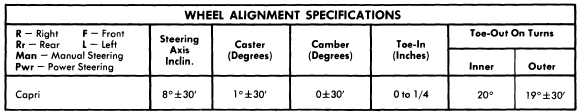
1970-73 CAPRI SPECIFICATIONS AND ADJUSTMENTS
TIRE INFLATION (COLD)
Before attempting to check or adjust wheel alignment, ensure that tires are properly inflated. Refer to manufacturers specifications located on right hand sun visor.
CASTER
All Models - Caster is nonadjustable. If not within specifications, check front suspension for damage. Repair or replace parts as necessary.
CAMBER
All Models - Camber is non adjustable. If not within specifications, check front suspension for damage. Repair or replace parts as necessary
TOE-IN
All Models - Position wheels in straight ahead position and loosen tie rod end lock nut and clips securing bellows. To adjust toe-in, rotate tie rods until specifications are within limits. Tighten lock nuts and secure clips. Tie rods should be equal within 1/4".
The New Improved and Re designed Auto Repair Savings My Special Links!
| 0 comments |Labels: and, auto, designed, improved, links!, my, new, re, Repair, savings, special, the

Hi everyone. I am Spencer aka Autodude, and I just wanted to welcome you here and let you know what is happening at the, “Auto Repair Savings Blog.” I hope you don’t mind the construction but when I’m through I am very sure you will like the new design! Happy Driving and Keep Your Car Tuned!
BMW 5 Series Service Manual
| 0 comments |Labels: 5, BMW, Manual, Series, service
Manufacturer: BMW
Model: 5-Series 525i, 530i, 535i, 540i, including touring,
Year: 1989, 1990, 1991, 1992, 1993, 1994, 1995
Quick Reference Index:
Model: 5-Series 525i, 530i, 535i, 540i, including touring,
Year: 1989, 1990, 1991, 1992, 1993, 1994, 1995
Quick Reference Index:

- General Data and Maintenance
- Engine
Engine-General, Engine Removal and Installation, Cylinder Head Removal and Installation, Cylinder Head and Valvetrain, Camshaft Timing Chain, Camshaft Timing Belt, Lubrication System, Ignition System--DME, Battery, Starter, Alternator, Fuel Injection--DME, Fuel Tank and Fuel Pump, Radiator and Cooling System, Exhaust System - Transmission
Transmission-General, Clutch, Manual Transmission, Automatic Transmission, Gearshift Linkage, Driveshaft - Suspension, Steering and Brakes
Suspension, Steering and Brakes - General, Front Suspension, Steering and Wheel Alignment, Rear Suspension, Final Drive, Brakes - Body
Body-General, Fenders and Engine Hood, Doors, Trunklid, Tailgate - Body Equipment
Exterior Trim Bumpers, Door Windows, Interior Trim, Central Locking, Seats, Sunroof - Electrical System
Electrical System - General, Fuses and Relays, Wipers and Washers, Switches and Electrical Accessories, Instruments, Exterior Lighting, Heating and Air Conditioning, Radio - Equipment and Accessories
Seat Belts, Air Bag System (SRS) - Electrical Wiring Diagrams
File Size: 61 MB
File Type: PDF, ZIP
Car Specifications
| 0 comments |Labels: car, specifications
Usually the first question that comes up is, "WHAT TYPE OF CAR DO YOU HAVE". This information gives the mechanic a quicker evaluation of your problem. With this he will began to evaluate the condition of your vehicle. It would be even more helpful if you had your vehicles Year Make and Model. An added bonus would be if you had your Engine Size handy.
This can be found on the schroud above the fan or on the hood it self. The mechanics will have to double check this while doing the repairs anyways so dont worry to much.
A dishonest mechanic can use this first conversation with you to determine if you are aware of your vehicles information. Their thinking is if you dont know your vehicles year make and model and engine size then you dont know really whats under your hood. So if all possible, have this information stored where you can have access to it when needed, like either your computer,
 Samsung NC10-13GB 10.1-Inch Blue Netbook - Up to 6 Hours of Battery Life
 laptop or your cell phone. Believe me the more knowledgable you seem concerning your car the less likely you will be ripped off!
In one of my earlier blogs I mentioned to ask to see your old parts when they are finished. Even know you dont know what your looking at, this gives the mechanics a sence that you are a very careful shopper!
If you havent got your own pocket scanner from Amazon you should plan on getting one real soon. I used it already 3 times in the past 3 months! Once for my car and 2 other times looking at friends and families vehicles. Somthing about the weather change brings on all kinds of car problems. Being able to bring in your own codes to your mechanic also shows him you care about your car and less likely to be scammed also.
So input your vehicles information some wheres so you can have it handy! Happy Driving!
Read More..
This can be found on the schroud above the fan or on the hood it self. The mechanics will have to double check this while doing the repairs anyways so dont worry to much.
A dishonest mechanic can use this first conversation with you to determine if you are aware of your vehicles information. Their thinking is if you dont know your vehicles year make and model and engine size then you dont know really whats under your hood. So if all possible, have this information stored where you can have access to it when needed, like either your computer,
In one of my earlier blogs I mentioned to ask to see your old parts when they are finished. Even know you dont know what your looking at, this gives the mechanics a sence that you are a very careful shopper!
If you havent got your own pocket scanner from Amazon you should plan on getting one real soon. I used it already 3 times in the past 3 months! Once for my car and 2 other times looking at friends and families vehicles. Somthing about the weather change brings on all kinds of car problems. Being able to bring in your own codes to your mechanic also shows him you care about your car and less likely to be scammed also.
So input your vehicles information some wheres so you can have it handy! Happy Driving!
Porsche 986 Boxter Owners Manual
| 0 comments |Labels: 986, boxter, Manual, Owners, porsche
Manufacturer: Porsche
Model: 986
Table of contents:

Model: 986
Table of contents:
- Controls and instruments
- Shifting Gear
- Mobile Roofs
- Maintenance
- Car Care
- Practical Tips
- Emergency Service
- Vehicle Identification
- Technical Data
- Index
File Size: 46 MB
File Type: PDF, RAR
1974 Capri Wheel Alignment
| 0 comments |Labels: 1974, alignment, capri, wheel
CAPRI SPECIFICATIONS AND ADJUSTMENT
TIRE INFLATION (COLD)
Before attempting to check or adjust wheel alignment, make sure that tires are properly inflated. Refer to manufacturers specifications, located inside glove box door.
CASTER
All Models - Caster is nonadjustable. If not within specifications, check front suspension for damage. Repair or replace parts as necessary.
CAMBER
All Models - Camber is non adjustable. If not within specification, check front suspension for damage. Repair or replace parts as necessary.
TOE-IN
All Models - Position wheels in straight-ahead position and loosen tie rod end lock nut and clips securing bellows. To adjust toe-in, rotate tie rods until specifications are within limits. Tighten lock nuts and secure clips. Tie rods lengths should be equal within 1/4".
1974 Capri Models

1975 Capri Models

Arrow 1976 77 Drive Axles Repair Manual
| 0 comments |Labels: 1976, 77, arrow, axles, Drive, Manual, Repair
Models Covered:
2) To remove axle bearing proceed as follows: Grind down bearing retainer at one point until retainer thickness is .04 - .06" (1.0 - 1.5 mm) then chisel ground portion and remove retainer. Using suitable bearing puller or press (CT-1120) remove bearing from axle.
(0-2.0 mm)..............................(2.0 mm)
Removal - Drain oil from rear axle differential housing, then disconnect propeller shaft. Pull out both rear axle shafts approximately 2 1/2". Remove differential gear housing mounting nuts and withdraw the differential gear carrier. It may be necessary to top outside of housing to break gear carrier loose.
Disassembly
Drive Pinion Assembly - 1) Hold end yoke with suitable tool (C-3281) and remove lock nut, then remove end yoke. Using a wheel puller, force out drive pinion with adjusting shim, rear inner bearing rce, spacer and preload adjusting shim.
REASSEMBLY AND ADJUSTMENT
Side Bearing Preload - Fit each side bearing into differential case leaving shims out; use suitable tool (CT-1102) for this procedure. Ensure side bearings are completely seated before proceeding. Install differential case assembly on gear carrier, then calculate the clearance bwetween side bearing outer race and gear carrier as shown in illustration. After obtaining clearance add .002" (.05 mm) preload figure to each side. Insert shims equally on both sides. Align gear carrier and bearing cap index marks, then tighten cap retaining bolts. Ring Gear Deflection - Attach a dial indicator to back side of ring gear and measure deflection. If ring gear has excessive deflection, correct position of assembly in relation to differential case and again perform measurement. Replace ring gear or differential case as necessary.
- Arrow
- Colt
DESCRIPTION
Rear axle is of the banjo type, utilizing the removable carrier style differential. Light weight construction joins split tubular housing for each side with center covers welded to axle housing. Final drive is of the hypoid style. Axle shafts are semi-floating type supported with bearings at their respective ends in axle housing. Bearings are fitted to axles with pressure type bearing retainers. Pinion bearing preload, side bearing preload, and pinion depth adjustments are made with shims while differential side gears are adjusted with spacers.
REMOVAL AND INSTALLATION
Axle Shaft and Bearings
Removal - 1) Raise and suitable support rear axle housing so rear wheels clear ground. Remove rear wheel and brake back plate nuts, then disconnect wheel cylinder brake line. Fix suitable puller set (CT-1003 and C-637) to lug studs and work slide hammer until axle shaft is free to be withdrawn. Set brake back plate with parking brake attached out-of-way. Using suitable tool (C-637 with hook) remove axle shaft oil seal.
| FIG. 1 MEASURING AXLE SHAFT DEFLECTION |
3) Using a dial indicator, inspect axle shaft deflection in three spots (see illustration). Replace axle shaft if specifications are exceeded.
Axle Shaft Deflection Table
Application Std. Value Service Limit
Point "A"............................. 0-.004"................................. .004"
(0-.10 mm)............................. (.10 mm)
Point "B"............................... 0-.002"................................. .002"
(0-.05 mm)..............................(.05 mm)
Point "C"............................... 0-.08"..................................... .08"
| FIG. 2 EXPLODED VIEW OF AXLE SHAFT ASSEMBLY |
4) Rear axle bearing should be replaced when bearing noise is detected, when bearing axial play exceeds .014-.016" (.36-.41 mm) or if bearing axial free play exceeds .001-.002" (.03-.04 mm) at approximately 11 lbs. (5.0 kg) measuring force.
5) Inspect wheel hub bolts for tightness and bearing outer retainer for deformation, replace parts as necessary.
Installation - 1) Fit outer bearing retainer for sie against shaft splined end, then install bearing and inner bearing retainer. Seat bearing retainer with smaller chamfered side directed to the bearing. NOTE - Ensure bearing is completely seated.
2) Lightly coat lips at oil seal and using suitable oil seal installer (DT-10078 and CT-1008) fit axle shaftt oil seal in rear axle housing.
3) Using packing and shim in proper sequence, set clearance between bearing and outer bearing retainer to .00-.01" (.0-25 mm).
4) Carefully insert axle shaft assembly into axle housing using care not to damage seal. Slightly turn axle shaft until splines line up with differential side gears. Align packing oil holes with outer bearing retainer and tighten bearing retainer to axle housing flange. Connect brake line to wheel cylinder and bleed air from system.
DIFFERENTIAL CARRIER
| FIG. 3 REMOVING DIFFERENTIAL GEAR HOUSING |
Installation - Lightly coat each bearing and gear with oil. Apply sealing compound on packing and axle housing seat, then assemble gear carrier to axle housing with nuts and tighten. Fill differential gear housing with .96 quart of suitable multi-purpose gear oil (API GL-5).
OVERHAUL
| FIG. 5 REMOVING DRIVE PINION BEARING |
Differential Gear Assembly - 1) Remove bearing carrier and lever gear case assembly form housing. Using suitable puller tool (C-293-P & C-293-39) pull differential side bearing. Keep right and left bearings and shim in sequence for reassembly.
2) Remove ring gear lock plate tabs and loosen bolts in diagonal sequence, then remove ring gear. Drive out pinion shaft lock pin from ring gear back side using a punch, pull out pinion shaft and pinion. Pinion side gears and spacers are now accessible. Note placement of pinion side gear and spacers and ensure they are reassembled in same position.
| FIG. 6 REMOVING DRIVE PINION FRONT BEARING OUTER RACE |
2) With suitable bearing puller (C-293-P & C-293-39) remove rear bearing inner race and at the same time, pull off drive pinion adjusting shim. Using suitable drift, remove front drive pinion bearing outer race and oil seal. Repeat same procedure to remove bearing outer race.
INSPECTION
Check differential gears for correct tooth contact and replace gears if wear is excessive. Inspect bearing faces for roughness or score marks and replace, if necessary, bearing assembly. Ensure splines of side gears and rear axle shafts fit correctly. Check clearance between pinion gears and pinion shaft, if wear is excessive, replace components.
NOTE - To check gear tooth contact using pain impression method, refer to beginning of this section.
| FIG. 7 EXPLODED VIEW OF COLT SEPARATE HOUSING REAR AXLE ASSEMBLY |
| FIG. 8 CHECKING DIFFERENTIAL PINION AND SIDE GEAR BACKLASH |
Case Assembly - 1) Install thrust washers (spacers) behind side gears in their original position and assemble pinion and side gears in differential. Insert both pinion gears, with pinion washers attached, so they mesh with side gears. It may be necessary to slightly rotate pinions to achieve desired meshing. Insert drive pinion shaft.
2) Check pinion and side gear backlash as shown in illustration, if backlash is beyond 0-.003" (0-.08 mm) adjust by selecting a side gear thrust washer (spacer) of correct size. If backlash is to be adjusted, ensure right and left sides are equally shimmed.
3) Thoroughly clean all dirt from ring gear mounting surface of differential case. Install bolts and lock washers. Tighten bolts alternately in a diagonal sequence and bend over lock tabs. Ensure lock washers are in contact with case rib after final torque has been performed.
Drive Pinion - Using a suitable drift and hammer or a press, seat front and rear bearing outer races into gear carrier ensuring that outer races do not cock. Ensure bearing races are completely seated before proceeding. Install shim between drive pinion and rear bearing. Using suitable bearing installer (CT-1075) press bearing onto drive pinion shaft. If drive pinion and bearings are scheduled to be reused, shims should be replaced with new ones of same thickness. In instances where the gear set is to be replaced, install new shims that are the same thickness as the used shims on drive pinion. NOTE - When determining the desired thickness of shim pack, amount of compression (sinkage) of shim pack and wear of the bearing (where old bearing is reused) must be taken into consideration.
Drive Pinion Depth - Install drive pinion spacer, front bearing, washer, end yoke and washer in order of removal. fit pinion shaft retaining nut and slowly tighten nut, continously checking, until pinion bearing preload is 6-9 INCH lbs. (7-10 cmkg) with oil seal not installed. Place suitable cylinder gauge on inside bearing pedestals of gear carrier housing. Place a block gauge on top end of drive pinion and slip a feeler gauge between the two gauges to obtain the correct clearance. The clearance between gauges should be .0118" (.300 mm). This is the standard height and any deviation from this height will be marked on the head of the pinion shaft and side of ring gear. To calculate the correct pinion height, add or subtract the variation value from the standard height.
NOTE - Stamped values are in hundredth millimeters. Add or subtract the correct amount of shims as necessary.
Pinion Bearing Preload - This adjustment must be performed after the setting of the drive pinion depth. Remove end yoke and insert the bearing preload adjusting shim between pinion spacer and bearing, then tighten end yoke to 9-11 INCH lbs. (10-13 cmkg). In addition to the preload adjusting shims there are spacers available to provide proper adjustment. After finishing adjustment of drive pinion bearing preload remove the end yoke and apply a thin coat of grease to outer surface of oil seal, then drive seal into position in gear carrier. After greasing oil seal lip, insert end yoke and tighten nut.
| FIG. 9 MEASURING CLEARANCE BETWEEN SIDE BEARING AND GEAR CARRIER |
Drive Pinion Backlash - Measure backlash of drive pinion in at least four different spots on ring gear with drive pinion securely fixed in final position. Set up a dial indicator on ring gear teeth edges. If measured backlash is greater than .005-.007" (.13-.18 mm), shift shims from ring gear side to back of the ring gear to obtain proper backlash. If the measure value is less than standard value, reverse the moving of shims as stated above. Side bearing shims are available in various thicknesses.
NOTE - Check gear tooth contact using point impression method described at beginning of this section.
Final Inspection and Assembly - Lightly coat each gear and bearing before and during reassembly with gear oil. After installing each component, ensure all rotating parts are free to move smoothly. Install differential gear assembly to axle housing after applying sealing agent and tighten gear carrier mounting nuts in diagonal sequence.
Pantera 1973 74 Wheel Alignment Repair Guide
| 0 comments |Labels: 1973, 74, alignment, guide, pantera, Repair, wheel
1973-74 PANTERA SPECIFICATIONS AND ADJUSTMENTS
TIRE INFLATION (COLD)
Before attempting to check or adjust wheel alignment, make sure tires are properly inflated. Refer to manufacturers specifications given in owners manual.
RIDING HEIGHT
NOTE - Vehicle must be loaded to simulate normal road condition, before attempting to check or adjust wheel alignment.
CASTER
Caster angle is not adjustable. If caster angle is not within specifications, inspect suspension system for wear or damage and repair or replace components as necessary.
CAMBER
Front - With normal loaded condition simulated, measure camber angle. If adjustment is necessary, loosen bolts on upper control arm ball joint. Move ball joint in or out to obtained specified angle. Tighten bolts.
Rear - If rear camber angle is not to specifications, adjust by adding or removing an equal number of shims between lower control arm attaching bracket and the frame. NOTE - An equal number of shims must be added or removed at both attaching brackets.
TOE-IN
Front - Set wheels in straight-ahead position and measure toe-in. If adhustment is necessary, loosen lock nuts on steering link (tie rods) adjusting sleeves. Rotate each sleeve on equal amount until correct toe-in is obtained. NOTE - After adjustment, both steering links (tie rods) should be of equal length.
Rear - Back vehicle onto alignment machine, and note that a toe-out condition will be indicated. If adjustment is necessary, loosen lower control arm attaching bracket both and insert horseshoe shims behind lower control arm attaching bracket. NOTE - After adjusting toe-in, thickness of shims should be about equal on each side of vehicle.
1973

1974

Tax Date
| 0 comments |Labels: date, tax
Results for Tax Date
Tax Calendars For 2011
File Form 945 To Report Held Income Tax For 2011. This Due Date Ap-income Tax Withheld For 2011 On All Nonpayroll Second Quarter Plies Only If You Deposited The Tax For The
http://www.irs.gov/pub/irs-pdf/p509.pdfKey Tax Deadlines For Tax Agents 2011-2012
Deadline For Filing Forms P9d, P11d, P11d(b), Or Substitutes For The Tax Year Ending 5 April 2011. 6. Last Date For Giving A Copy Of The 2010-11 Forms P9d, And Forms
http://www.hmrc.gov.uk/agents/tax-deadlines.pdfDistrict Taxes, Rates, And Effective Dates
California City And County Sales And Use Tax Rates N ***october*2011 Page 4 District Taxes, Rates, And Effective Dates* Tax Area District Name And Initials Rate Effective Date End
http://www.boe.ca.gov/sutax/pdf/districtratelist.pdf2011 California Instructions For Form 100-es
If The Qsub Is Acquired During The Taxable Year, The Qsub Annual Tax Is Due With The S Corporations Next Estimated Tax Payment After The Date Of The Qsub Election.
http://www.ftb.ca.gov/forms/2011/11_100esins.pdf2012 Property Tax Calendar
2012 Property Tax Calendar * If A Due Date Falls On A Saturday, Sunday, Or Legal Holiday, That Due Date Becomes The Next Business Day. (rcw 1.12.070) January 1
http://dor.wa.gov/Docs/Pubs/Prop_Tax/PropCal.pdfForm 4, Application For Extension Of Time To File Michigan Tax Returns
For Most Individual Income Tax Filers, This Date Is 12-2011. Fiscal Year Filers: See Supplemental Instructions For Standard Fiscal Mbt Filers On Page 145 Of Form
http://michigan.gov/documents/4_144975_7.pdfProperty Tax Due Dates & Appeal Deadlines
Apr 30 South Dakota Re Tax Bills Due - 1st Half Installment. Apr-may Tennessee Re Value Notices Issued - 40% Assmt. Ratio. Apr - May Texas Re Value Notices Issued Apr
http://www.transporttax.com/documents/PropertyTaxDates.pdfArkansas Excise & Income Tax Due Dates 2010 Tax Calendar For Small
Arkansas Excise & Income Tax Due Dates 2010 Tax Calendar For Small Businesses
http://www.dfa.arkansas.gov/Documents/dueDateCalendar.pdfOklahoma Sales Tax Report
Line 19 (penalty) - If This Tax Report And Remittance Is Not Postmarked Within 15 Calendar Days Of The Due Date, A 10% Penalty Is Due. Multiply The Tax Amount On Line 16
http://www.tax.ok.gov/btforms/13-23.pdf2012 Tax Calender
West Virginia State Tax Department 2012 Tax Calendar Org. 1/12 Due Date Form Form Title Comments January 10 Wv/brw-01 Brewer/importer/manufacturer Beer
http://www.state.wv.us/taxrev/publications/taxCalendar.pdfTax Due Date Calendar 2011-2012
Ir 328 February 2011. Ir 328 February 2011 Employer Deductions (edf/ir 345) Form And Payment Due And Employer Monthly Schedule (ems/ir 348) Due Note: This Calendar
http://www.ird.govt.nz/resources/7/d/7d8ab880423855ca901a9d82245c33b7/ir328.pdfTax Payments Checklist (yeartodate Payroll)
Tax Payments, Year-to-date Payroll (9/4/2008) Page 1 Of 8 Tax Payments Checklist (yeartodate Payroll) Important : Before You Enter Tax Payments In The Enter
http://http-download.intuit.com/http.intuit/CMO/payroll/support/PDFs/Misc/YTD_Tax_Checklist.pdf2011 Tax Return Filing Due Date
1 Maine Tax Alert A Publication Of Maine Revenue Services For Tax Professionals Volume 21, No. 6 September, 2011 (2 Nd Issue) Public Communications Tel: (207) 626
https://maine.gov/revenue/publications/alerts/2011/TASep2011_2_Vol21_Iss6.pdfEmployers Return Of Virginia Income Tax Withheld Form Va-5
Pay The Tax After The Due Date, A Penalty Is Assessed. The Penalty Is 6% Of The Tax Due For Each Month Or Fraction Of A Month, Not To Exceed 30%.
http://www.tax.virginia.gov/taxforms/Business/Withholding%20Tax/VA-%205%20Quarterly.pdf2010 Withholding Tax Return And Payment Due Dates
Any Additional Tax Due Must Be Paid On Or Before The Due Date Of The Monthly Tax Return. All Employers Subject To The Requirement Of Quarter-monthly Filing Must File And
http://dor.mo.gov/forms/efile.pdfForm Ct-5-i:2010:instructions For Form Ct-5 Request For Six-month
However, If, At A Later Date, You Need To Establish The Date You Filed*or*paid*your*tax,*you*cannot*use*the*date*recorded*by*a* Private Delivery Service Unless You Used A
http://www.tax.ny.gov/pdf/current_forms/ct/ct5i.pdfOklahoma Annual Franchise Tax Return
Frx 0600202 000 L. Frx0002-05-1999-bt Form 200 Revised 6-2006 Oklahoma Annual Franchise Tax Return A. Taxpayer Fein B. Reporting Period C. Due Date 1 2 3 4 5 6 7
http://www.tax.ok.gov/oktax/btforms/200long-06.pdfState Of Georgia Department Of Revenue
All Wages Paid During The Calendar Quarter Should Be Reported On The Same Form G-7/schedule B Listing The Tax Withheld For Each Pay Date Of The Quarter.
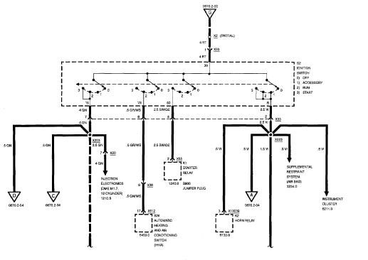
https://etax.dor.ga.gov/taxguide/TSD_Employers_Withholding_Tax_Guide_2011.pdfBMW 850i 1991 Electrical Repair
| 0 comments |Labels: 1991, 850i, BMW, electrical, Repair
Electrical Troubleshooting Manual, Schematics and Wiring Diagrams For
Manufacturer: BMW
Model: 850i E31
Year: 1991
Quick Reference Index:

Manufacturer: BMW
Model: 850i E31
Year: 1991
Quick Reference Index:
- Introduction/ Symbols
- Power Distribution and Fuse Chart
- Fuse Details, Ground Distribution
- Data Link
- Engine Control System (DMEM1.7, 12-Cylinder M70)
- Electronic Throttle Control System (EML 12-Cylinder)
- Start and Charging System
- Power Assist Steering (Servotronic)
- Electronic Shock Absorber Control (EDC III+)
- Electronic Transmission Control (EGS)
- Supplemental Restraint System (Airbag)
- Slip Control (ABS)
- Power Mirrors
- ZKE: Door Lock Heating (TSH), Central Locking (ZV), Power Windows (FH)
- Power Seats and Lumbar Support. Heated Seats
- Power Sunroof (SHD), Central Body Electronics (ZKE IV)
- Horn, Drive-Away Protection (EWS II)
- Wiper/ Washer Module (WWM)
- Headlight Washer (SRA)
- Windshield Washer Jet Heaters
- Instrument Cluster, Clock, Light Switch Details Headlights, Fog Lights
- Turn/ Hazard Lights/ Park/ Tail/ Underhood Lights
- License Plate/ Luggage Compartment Lights
- Back up Lights, Brake Lights, Interior Lights, Interior Accessories, Crash Control Module
- Rear Window Defogger, Integrated Heating-Climate Control
- Radio/ CD Player (Provisions)/ HIFI
- Cellular Telephone (Provisions)
- Cruse Control (Tempomat), Anti-theft System (ALPINE)
- Board Computer (BC-LOW)
- Component Location Chart and Views
- Splice Location Views, Connector Views
File Size: 8 MB
File Type: PDF, ZIP
Nissan Pathfinder WD21 1994 Repair Manual
| 0 comments |Labels: 1994, Manual, Nissan, pathfinder, Repair, wd21
Manufacturer: Nissan
Model: Pathfinder WD21 Series 1st Generation
Year: 1994
Engine:2.4 L Z24i I4106 hp (79 kW)
2.4 L KA24E I4 140 hp (100 kW)
3.0 L VG30i V6 145 hp (108 kW)
3.0 L VG30E V6 153 hp (114 kW)
2.7 L TD272 I4 Diesel 84 hp (63 kW)
2.7 L TD27T2 I4 Turbodiesel 99 hp (74 kW)
2.7 L TD27T4 I4 Turbodiesel 113 hp (84 kW)
Quick Reference Index:
Read More..
Model: Pathfinder WD21 Series 1st Generation
Year: 1994
Engine:2.4 L Z24i I4106 hp (79 kW)
2.4 L KA24E I4 140 hp (100 kW)
3.0 L VG30i V6 145 hp (108 kW)
3.0 L VG30E V6 153 hp (114 kW)
2.7 L TD272 I4 Diesel 84 hp (63 kW)
2.7 L TD27T2 I4 Turbodiesel 99 hp (74 kW)
2.7 L TD27T4 I4 Turbodiesel 113 hp (84 kW)
Quick Reference Index:

- General Information
- Maintenance
- Engine Mechanical
- Engine Lubrication and Cooling Systems
- Engine Fuel and Emission Control Systems
- Accelerator Control, Fuel and Emission Control Systems
- Clutch
- Manual Transmission
- Automatic Transmission
- Transfer
- Propeller Shaft and Differential Carrier
- Front Axle and Front Suspension
- Rear Axle and Rear Suspension
- Brake System
- Steering System
- Body
- Heater and Air Conditioner
- Electrical System
- Alphabetical Index
File Size: 33 MB
File Type: PDF, ZIP
Mazda Millenia 1996 Workshop Manual
| 0 comments |Labels: 1996, Manual, Mazda, millenia, Workshop
Manufacturer: Mazda
Model: Millenia
Year: 1996
Contains the following information and repairs for:

Model: Millenia
Year: 1996
Contains the following information and repairs for:
- General Information
- Engine (KJ and KL)
- Lubrication System
- Cooling System
- Fuel Emissions and Control Systems
- Engine Electrical System
- Automatic Transaxle (GF4A-EL and LJ4A-EL)
- Front and Rear Axles
- Steering System
- Braking System and Traction Control System
- Wheels and Tires
- Suspension
- Body
- Body Electrical System
- Heater and Air Conditioning
File Size: 48 MB
File Type: PDF, RAR
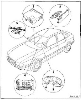
Audi 80 1992 Electrical Diagrams
| 0 comments |Labels: 1992, 80, audi, diagrams, electrical
Manufacturer: Audi
Model: 80
Year: 1992
Quick Reference Index:
Model: 80
Year: 1992
Quick Reference Index:

- Self-Diagnosis
- Starter
- Current Supply
- Gauges
- Instruments
- Radio
- 2-Way Radio
- Telephone
- Windscreen Wipers
- Wash Sysetm
- Lights, Lamps, Switches - Interior and Exterior
- Wiring
File Size: 5.83 MB
File Type: PDF
Mazda RX 7 1993 Owners Manual
| 0 comments |Labels: 1993, 7, Manual, Mazda, Owners, rx
Manufacturer: Mazda
Model: RX-7
Year: 1993
Table of Contents
Model: RX-7
Year: 1993
Table of Contents
 |
| Mazda RX-7 Interior |
- Your Vehicle at a Glance
- Knowing Your Mazda
- Protecting Your Mazda
- Driving Your Mazda
- In Case of Emergency
- Appearance Care
- Maintenance
- Customer Information (Including Information on How to Report Defects)
- Specifications
- Index
File Size: 76 MB
File Type: PDF, RAR
Auto Repair Beware of Skeezy Technicians
| 0 comments |Labels: auto, beware, of, Repair, skeezy, technicians
Taking your car to the mechanic can be a frustrating experience. Most people no little if anything about car repair, leaving them at the mercy of the mechanic. While many mechanics are reputable professionals, there are also many who pull quick scams in order to make a fast buck and keep your car coming back for repairs indefinitely. Here are some common auto repair scams to keep a look out for the next time you bring your car in for a service.
Not Doing the Job
Many auto mechanics simply cant get the job done right. While no mechanic is perfect and sometimes fixing a problem takes a bit of trial and error, others simply dont perform the required auto repairs. Look for auto shops with good customer service policies such as warranties and free estimates. Its also wise to ask the mechanic to show you what was done and explain it to you. If youre having a new part installed, ask to receive the old part along with the packaging for the replacement to ensure you got what you paid for.
Extra Work
You brought your car in for a tune up and ended up with an outrageous bill. Some auto repair con artists will try and convince you that they performed necessary and important repairs without your express permission. No repair should be performed without consulting the owner first. You should also get everything in writing. Be wary of charges that greatly exceed the estimate as well.
Premium Prices
Many auto repair shops have a "dont ask, dont tell" policy when it comes to the type of parts they order. They often choose the most expensive, and most people are so clueless about cars that they agree. The internet gives you a cheap and fast way to shop around for prices. Ask what part is needed and then do a search on your own before having the repair done. You may bring in the part yourself and just pay for the labor if you find a better price. You can also ask to have a used part instead of a new part.
Multiple Estimates
Some people are so desperate to get their cars back on the road that they drop them off at the first auto repair shop they find. This can put a huge dent in your wallet. Visit two or three different shops and youre likely to find great discrepancies in the prices, possibly even by hundreds of dollars. Youre also likely to get different opinions on what repairs need to be performed.
Unnecessary Repairs
Sometimes scam artist auto repair mechanics will try and convince you that you need extra repair work done. While some may be legitimate suggestions, its good to check around and see how often certain parts should be changed. Its also good to keep records of all your repairs and tune-ups so you can check to see what has been performed recently. If you just had your air filter replaced and you find a shop owner is insistent you need a new one, time to find a new mechanic.
Saving More Money on Your Car Repairs Tips and Advice
| 0 comments |Labels: advice, and, car, money, more, on, repairs, saving, tips, your
Saving More Money on Your Car Repairs: Tips and Advice
Saving money on your car repairs should be a high priority in todays economy. Make sure you have a plan of action when it comes to your car repairs.
Read More..

Saving money on your car repairs should be a high priority in todays economy. Make sure you have a plan of action when it comes to your car repairs.

Traveling
| 0 comments |Labels: traveling
Take your car to your regular mechanics shop two weeks prior to your trip. Hopefully you have a regular mechanic that you know and trust. This should NOT be a quick-lube type place, but a full service repair shop or new car dealership. I personally would not want to test the workmanship of a new mechanic on a road trip with my family.
Two weeks prior? Definitely. Give your mechanic time to make necessary repairs, and some room for adjustments. If your mechanic finds problems and repairs parts on your vehicle, you will want a week or so "break in period" to test the fix(s) before you hit the road. In most cases, if anything goes wrong after major repairs, it will be in the first 100-200 miles. Give yourself enough time to feel confident that the repairs made will not be an issue as soon as you get outside your city limits. Keep all receipts just in case the part fails along the way, so you don’t have to buy it again.
Make sure that you have the following items in your car before you leave:
Flashlight, pen, paper, and disposable camera. Just in case of an accident, take lots of pictures of the scene, the other car involved (including license plate), the other driver , and anyone else in their car, etc. Take pictures of the road condition i.e. was it wet, was there an obstacle in the road that could have caused the accident, was it at a intersection with a stop sign or traffic light, if at night was it lit and well marked? Get business cards or contact information from anyone that could be a witness, and if at all possible get them to give their statement to the police officer at the scene. It seems that a few days after an accident the memory of small details becomes cloudy and unclear to some people, and in worst cases the story of how, where, and who was involved in the accident can become fabricated.
Take along some extra supplies that your car might need while on the road. A new bottle of anti-freeze, engine oil, and transmission fluid could really come in handy if a roadside emergency were to occur. A can of Fix-A- Flat, jumper cables, small box of tools including screw drivers, pliers, a few spare radiator hose clamps that you can get from your mechanic, roll of electrical tape, and a hand towel to wipe your hands should all be packed in your car. Fix-A-Flat should only be used in case of an emergency and not to be used just to add a small amount of air to the tires. Fix-A-Flat and other products like it require that the tire be removed from the wheel, and the product be removed from inside the tire and a permanent repair be preformed. Caution: Some tire sealants are flammable and all are very messy and sticky, so you will appreciate the towel to wipe off your hands. One more device for the more technical aspect of it would be a Test light to check your fuses. A Blown fuse can cause all kinds of problems! Such as fuel pump not working, headlight not working, dash lights not operating at night or your blinkers quit working etc.
A few recommendations that will aid in driver comfort are: Install new wiper blades and fill up the washer bottle with windshield washer solvent to help keep the windshield clean (seems wiper blades are never thought about unless it is raining). Bring along sunglasses, a few of your favorite music cds or cassettes, wear comfortable clothes and shoes, and bring a jacket and rain gear just incase you have to be outside your vehicle for an emergency situation. A cell phone is a very helpful tool to have on your travels, but make sure you will have reception in the region you are traveling in, and dont forget the battery charger. Some cell phone companies offer roadside assistance for its customers, call your cell phone service provider and see if this service is offered. If you know where your going, find the number for a Tow truck driver and program it in your cell phone just in case.
Have your mechanic perform all regular scheduled maintenance on your car before you head off on your travels, and make sure to tell him where you will be going. If I know that you are going to be traveling in a hilly, snowy location pulling a small trailer I would make sure to inspect items that would be more prone to cause trouble in that kind of situation. Traveling through a hot arid dessert would require a different inspection than a winter trip. Drive safe and be sure to check out my amazon.com special link for more automotive needs! Thanks!
Nissan Frontier D22 2001 Repair Manual
| 0 comments |Labels: 2001, d22, frontier, Manual, Nissan, Repair
Manufacturer: Toyota
Model: Frontier D22 Series
Year: 2001
Quick Reference Index:
Model: Frontier D22 Series
Year: 2001
Quick Reference Index:

- General Information
- Maintenance
- Engine Mechanical
- Engine Lubrication and Cooling Systems
- Engine Control System
- Accelerator Control, Fuel and Exhaust Systems
- Clutch
- Manual Transmission
- Automatic Transmission
- Transfer
- Propeller Shaft and Differential Carrier
- Front Axle and Rear Axle
- Front and Rear Suspension
- Brake System
- Steering System
- Restraint System
- Body and Trim
- Heater and Air Conditioner
- Starting and Charging Systems
- Electrical System
- Alphabetical Index
File Size: 54 MB
File Type: PDF, ZIP
Subscribe to:
Posts (Atom)